Erroneous but Accurate Objects in FOMO Result

Project ID: 181184

Why does FOMO return 2 objects present when only one object is actually present in the camera frame 50% of the time?

I am running a vision FOMO model with one trained object in the frame. When I run the model on device repeatedly with the same input I am getting a result of 2 objects or Bounding Boxes (BB) in the frame about 50% of the time.

The Class 0 object is detected as follows:

Prediction 0.984, {x=56, y=24}, BB {8,32}

image

The Class 1 object is detected as follows:

Prediction 0.500, {x=72, y=56}, BB {8,8}

image

What is interesting is that the 2nd FOMOed object (Class 1) always has

  • a lower prediction score than the Class 0 object,
  • is usually well above EI_CLASSIFIER_OBJECT_DETECTION_THRESHOLD, and
  • is always 8x8 in size.

Also, note that the 2nd BB is accurate and lands on the trained object.

The distribution of the Classifications look like:

image

The EI_CLASSIFIER_OBJECT_DETECTION_THRESHOLD = 0.500.

@MMarcial

Great work on the investigative work. I like the distribution plot.
Regarding the the size always being 8x8, this and more is explained in FOMO - Expert mode tips.

To understand the problem more, are class 0 and class 1 similar? Seeing that class 1 is identified here too. Is the problem more so that the second idenitied object should be part of class 0?

What’s your thoughts @matkelcey?

During training FOMO bounding boxes get reduced to just the cell with the bounding box centroid. During inference there is some post processing that is done to fuse adjacent activations. I think that’s what’s happening in the first image; each of those three stacked cells look like the centroid of a screw.

As @rjames mentions; can you describe what class0 vs 1 are?

@rjames What do I mean by a Class?

I found this example code along the way somewhere now forgotten (so I assumed this is what EI called a Class).

After a FOMO run_classifier() is called, a loop is run:

for (size_t ix = 0; ix < EI_CLASSIFIER_OBJECT_DETECTION_COUNT; ix++)
    {

ix is the Class number, e.g., if ix=0 then this is Class 0.

So in the case of the 2nd image above you see a CLass 0 BB and a CLass 1 BB.

Please advise as to the correct definition as to what I am calling a Class.


@matkelcey Are you saying the BBs (given the default FOMO cfg) should all be 8x8? The docs seems to indicate that FOMO only identifies the centroid but I have a ton of data showing this is not true in that the BBs are not a mere 8x8.

For the dataset presented above this is the BB size distribution:

As you can see Class 0 does not have any 8x8 BBs!

I also have another FOMO project that runs on Python using the EI Runner against an EIM file that seems to me to clearly draw bounding boxes not centroids. My ask is here but got zero traction.


For clarification when I draw the BB on the image I am doing so in the above mentioned loop. So if I find a Class 0 BB I draw the BB as defined by &ei_result.bounding_boxes[0].{x,y,width,height} and save the image as a BMP. Then if I find a Class 1 BB I draw the BB as defined by &ei_result.bounding_boxes[1].{x,y,width,height} and save the image as a BMP. I do not erase the Class 0 BB so that I can see the BB locations relative to each other.

No sorry, we’re asking what has been labelled as class 0 vs 1? I’m guessing class 0 represents the semantic class “screw”, but we’re not sure what have you labelled as class 1?

In terms of the centroid / bounding box relationship; the model is trained with just the centroids of the bounding boxes ( from training data ). It’s at inference time we fuse these centroid detections back together. Your first image is a great example of this; you can split that single (8, 32) detection into 4 vertically stacked (8, 8) detections, each of which independently looks the centroid of a screw. The raw output of the FOMO model was the x4 (8, 8) detections, after fusing it’s a single (8, 32) detection.

Have a search in code for fill_result_struct_from_cubes for the fusing code.

And see https://www.edgeimpulse.com/blog/announcing-fomo-faster-objects-more-objects for some more info on the FOMO cells vs bounding boxes.

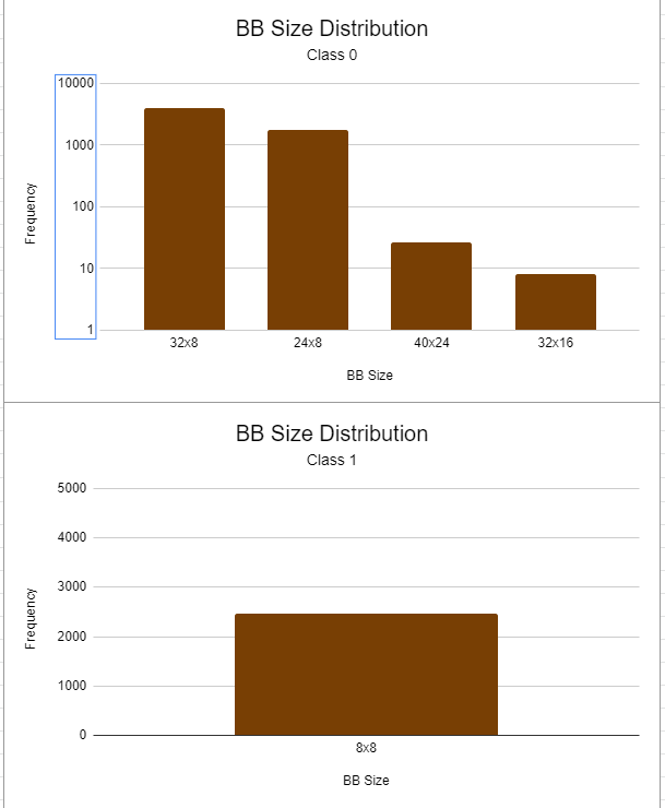
Yes, it seems the Class 1 should be part of Class 0.


To answer your question regarding, “we’re not sure what have you labelled as class 1?”, I will explain with an example. Note that my Impulse only has one output called screw.

Given this code:

run_classifier(&signal, &ei_result, debug);
FOMO_Count = 0;
for (ix = 0; ix < EI_CLASSIFIER_OBJECT_DETECTION_COUNT; ix++)
{
  if (ei_result.bounding_boxes[ix].value > 0)
  {
    FOMO_Count = FOMO_Count  + 1;
  }
}

Then FOMO_Count is the number of Classes found, i.e., is the count of Bounding Boxes (BBs) or screws that FOMO found.

If FOMO_Count = 1, then only Class 0 exists.
If FOMO_Count = 2, then only Class 0 and Class 1 exists.
If FOMO_Count = 3, then only Class 0 and Class 1 and Class 2 exists.
Etc.

Class in this context allows us to reference the various BBs in the FOMOed image.


The code under fill_result_struct_from_cubes() helped explain the BB sizes being returned from a FOMO model.

FYI: The code at fill_result_struct_from_cubes() also explains why bounding_boxes_count is always equal to 10 when the number of FOMOed objects is less than EI_CLASSIFIER_OBJECT_DETECTION_COUNT. Likewise, the doc stating, "The exact number of bounding boxes is stored in bounding_boxes_count field of ei_impulse_result_t" is not completely accurate.


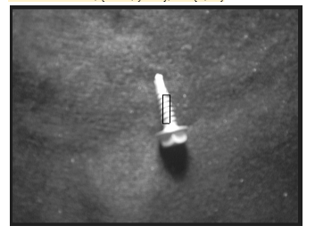
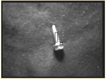
Regarding the size of the BBs found by FOMO, consider that part of this issue resolved. I ass-u-me-d that when I saw the Edge Impulse images of Jan’s beer bottles and the image of bees that FOMO was returning a single centroid but I now believe that FOMO is returning one or more fused Bounding Box(s) located around a central centroid.

My assumption was that the beer bottle image and the image of bees was a direct output of FOMO. This is not the case. The images have circles placed on a centroid that was derived from the FOMO Bounding Box output.


My original question still stands. How do I stop FOMO from counting the same screw more than once which is happening about 1/2 of the time in the referenced dataset?

@MMarcial,

These are not classes but objects. You’re looping through the list of detected objects. Note that within a single frame you may have multiple objectes detected of the same class/label. You can see this if you print ei_result.bounding_boxes[ix].label. My suspicion is that second object detected in your second image has the same label as the first detection.

And as @matkelcey mentioned, the model is trained on centroids but in the SDK we fuse nearby detected detections into larger single detections in ei_cube_check_overlap. The detections are then converted into bounding boxes in fill_result_struct_from_cubes.
The reason you see centroids with FOMO in Jan’s video is because on the GUI we process the boxes (sent from fill_result_struct_from_cubes) differently (for FOMO) to create the centroids. You can see the same when using the live preview of edge-impulse-linux-runner. See edge-impulse-linux-cli/webserver.js at master · edgeimpulse/edge-impulse-linux-cli · GitHub

1 Like

Oh yes, thanks @rjames, I did misread that snippet. Yes, these two are detections, not distinct labels.

In order of difficulty ( though not necessarily impact… )

  1. Use a higher cut point in MobileNet. see cut point . The sweet spot for FOMO is when the object of interest is the same size as the raw detections so that no fusing is required. So taking less of Mobilenet, we have a coarser output grid, which will match the size of your screws more. ( Note: if you take less of MobileNet you probably want to increase classifier capacity to compensate for the reduction of params. )

  2. Customise your fusing. You’ll see in the fill_result_struct_from_cubes there are some examples of configuration such as object_detection_threshold that allow more, or less, fusing of detections. Sounds like you want more aggressive fusing.

1 Like

Given: FOMO uses MobileNetV2 as a base model for its trunk and by default does a spatial reduction of 1/8th from input to output (e.g. a 96x96 input results in a 12x12 output).

Question: Does that mean the object, a screw in this case, should fit within a 12x12 cell?

That’s right; and by changing the cutpoint, or adding your own convolutions etc, you can change that 1/8th reduction to be something more specific.