Why do Arduino Accelerometer Examples limit range to -/+ 2G?

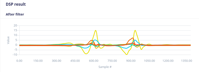
I’m working on an impulse that uses an accelerometer with a range of +/- 16G (the LSM6DSO). And my impulse has recorded data using that range. Here is a typical feature sample:

(Note I have 2 IMUs on this project. This is collecting accX1,accY1,accZ1,accX2,accY2,accZ2; hence the 6 lines.)

Now in the exported Arduino examples, there is this line near the top:

#define MAX_ACCEPTED_RANGE  2.0f        // starting 03/2022, models are generated setting range to +-2, but this example use Arudino library which set range to +-4g. If you are using an older model, ignore this value and use 4.0f instead

Which later down in the example code is used to cap the data that is saved into the buffer:

        IMU.readAcceleration(buffer[ix], buffer[ix + 1], buffer[ix + 2]);

        for (int i = 0; i < 3; i++) {
            if (fabs(buffer[ix + i]) > MAX_ACCEPTED_RANGE) {
                buffer[ix + i] = ei_get_sign(buffer[ix + i]) * MAX_ACCEPTED_RANGE;
            }
        }

I’m trying to figure out why this is. The nano_ble33_sense-accelerometer.ino example does this, but the Nano BLE33 Sense uses a LSM9DS1 IMU, which is also capable of +/-16G.

Why does the cap used in the examples set such a low max range?

The code comment implies that the model itself is limited to +/-2G. But if a model is a “Fusion” model like mine (since there are 6 axes rather than 3), does that limit somehow get applied anyway?
I think I figured out the question to my own answer. The inference example code is limited to +/-2G because the firmware for data collection also caps the Arduino Nano BLE 33 Sense to the same limit.

See the ei_lsm9ds1.cpp file in the GitHub Repository for the Nano 33 BLE Sense. This line in particular:

  writeRegister(LSM9DS1_ADDRESS, LSM9DS1_CTRL_REG6_XL, 0x60); // 119 Hz, 2G

Setting that register configures the LSM9DS1 to limit itself to +/-2G.

I also did not realize that the this firmware does conversion from Gs to MS2, with this section:

    if (ei_IMU.accelerationAvailable()) {
        ei_IMU.readAcceleration(imu_data[0], imu_data[1], imu_data[2]);

        imu_data[0] *= CONVERT_G_TO_MS2;
        imu_data[1] *= CONVERT_G_TO_MS2;
        imu_data[2] *= CONVERT_G_TO_MS2;
    }

I thought Edge Impulse was doing something special in the model to convert data to MS2, but it turns out the data is converted to MS2 before its even collected.

But if a model is a “Fusion” model like mine (since there are 6 axes rather than 3), does that limit somehow get applied anyway?

The answer is no. The limit to 2Gs only applies if the data fed into the model was also limited to 2Gs. Since my ingested data is up to 16Gs, the MAX_ACCEPTED_RANGE should also be changed to 16.0f. Or because I know the IMU will never record more than 16 anyway, I can remove the entire block of code.

So, if you’re like me and are ingesting from a non-supported board and are sending in raw G-values (not MS2 values) and your range is not limited to 2G, then this example code from the Arduino examples:

        IMU.readAcceleration(buffer[ix], buffer[ix + 1], buffer[ix + 2]);

        for (int i = 0; i < 3; i++) {
            if (fabs(buffer[ix + i]) > MAX_ACCEPTED_RANGE) {
                buffer[ix + i] = ei_get_sign(buffer[ix + i]) * MAX_ACCEPTED_RANGE;
            }
        }

        buffer[ix + 0] *= CONVERT_G_TO_MS2;
        buffer[ix + 1] *= CONVERT_G_TO_MS2;
        buffer[ix + 2] *= CONVERT_G_TO_MS2;

Can be shortened down to simply:

        IMU.readAcceleration(buffer[ix], buffer[ix + 1], buffer[ix + 2]);

I’d be curious to know why Edge Impulse does all of this manipulation when going into the model and then again when collecting the data to be inferred; when it could use the values right out of the accelerometer. But I think my primary question has been solved.