On STM32 using STM32Cube.MX (edgeimpulse.com)
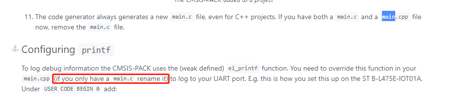
The above link page have some description as follows,
But I only rename the “main.c” into “main.cpp”, it will create some errors .
arm-none-eabi-gcc -o “adc.elf” @“objects.list” -mcpu=cortex-m4 -T"E:\Stm32Adc-EdgeImpulse-CubeIDE\STM32L431RCTX_FLASH.ld" --specs=nosys.specs -Wl,-Map=“adc.map” -Wl,–gc-sections -static --specs=nano.specs -mfpu=fpv4-sp-d16 -mfloat-abi=hard -mthumb -u _printf_float -Wl,–start-group -lc -lm -Wl,–end-group
c:\st\stm32cubeide_1.6.1\stm32cubeide\plugins\com.st.stm32cube.ide.mcu.externaltools.gnu-tools-for-stm32.9-2020-q2-update.win32_1.5.0.202011040924\tools\arm-none-eabi\bin\ld.exe: Startup/startup_stm32l431rctx.o: in function LoopFillZerobss': E:/Stm32Adc-EdgeImpulse-CubeIDE/Debug/../Startup/startup_stm32l431rctx.s:114: undefined reference to main’
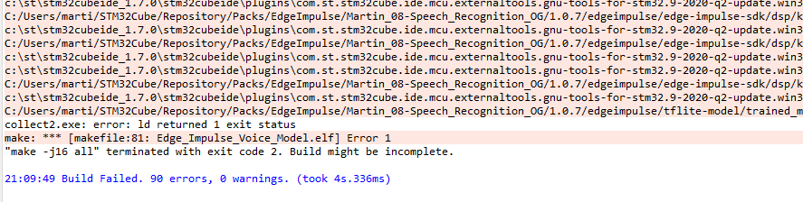
collect2.exe: error: ld returned 1 exit status
make: *** [makefile:65: adc.elf] Error 1
“make -j12 all” terminated with exit code 2. Build might be incomplete.
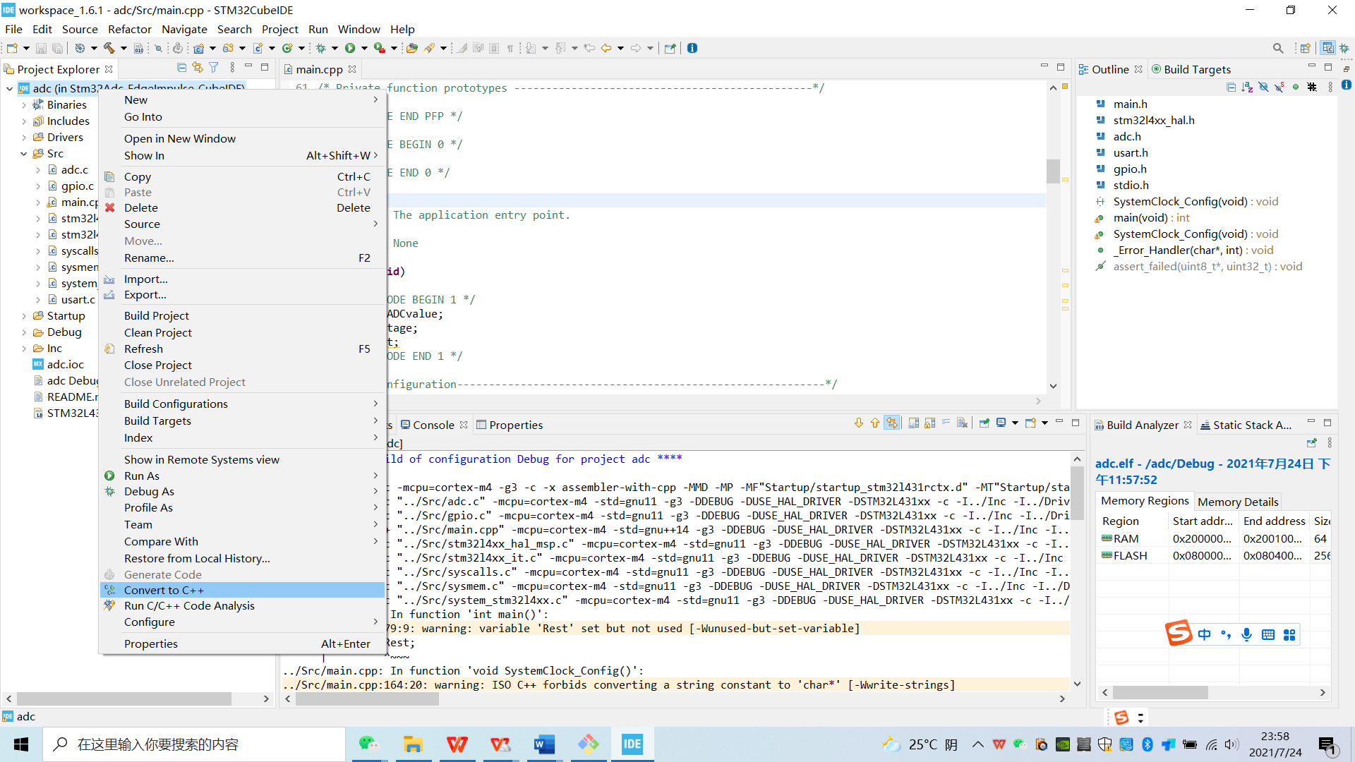
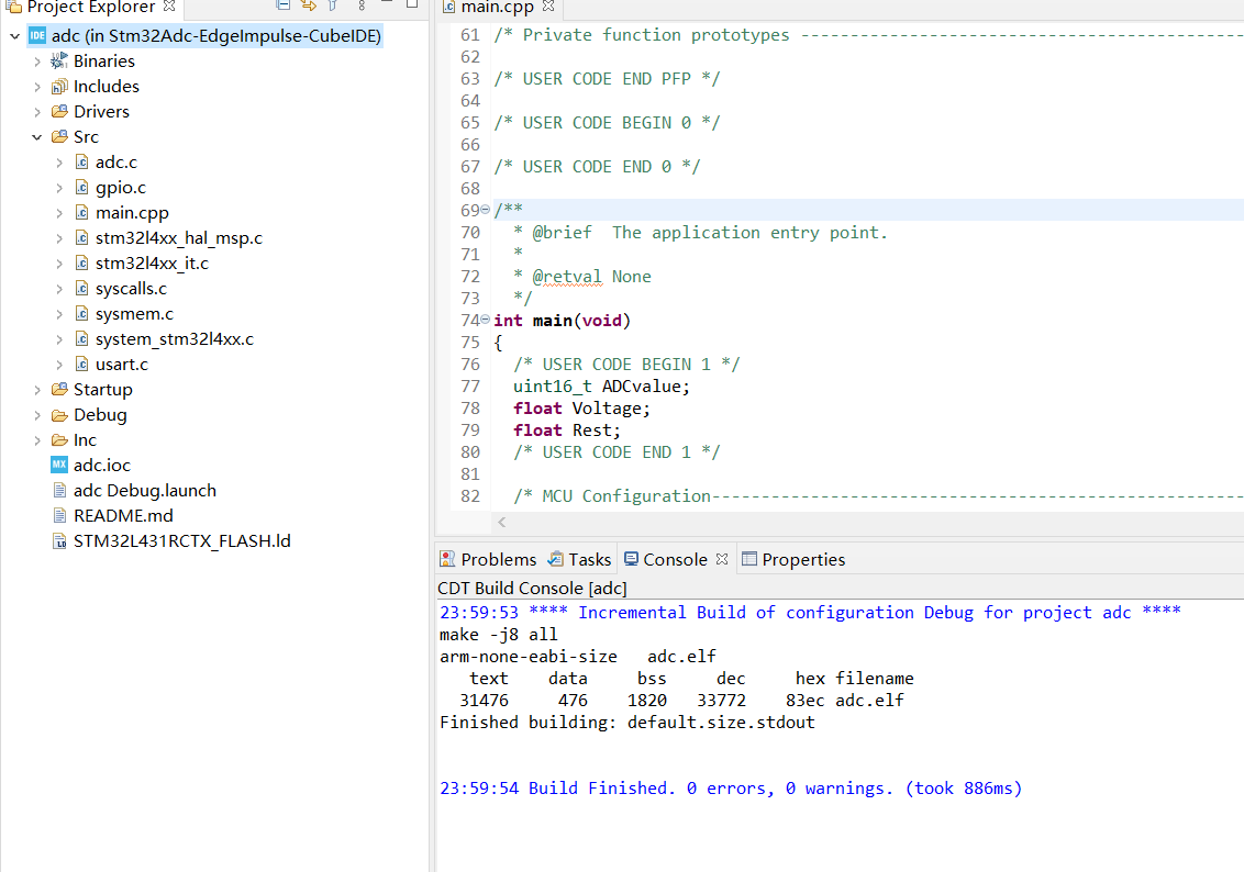
This picture is my debug information
@davwang Did you switch the project to be a C++ project? Right click on the project and it should show up.
Thanks for your help! This issue is ok now!
2 Likes
Hi Guys,
I’m having a similar issue with a custom voice commands model. I’m using the STM32 Discovery IoT Kit (based on STM32L475). I’m following the instructions from the following guide:
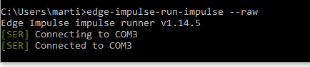
My issue is that the printing functions are not outputting anything in PuTTY or the Edge-Impulse-Cli.
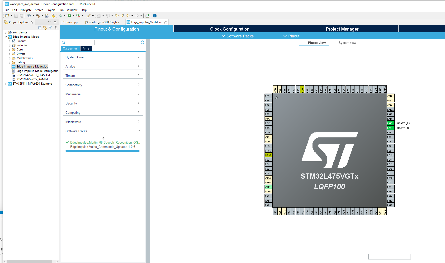
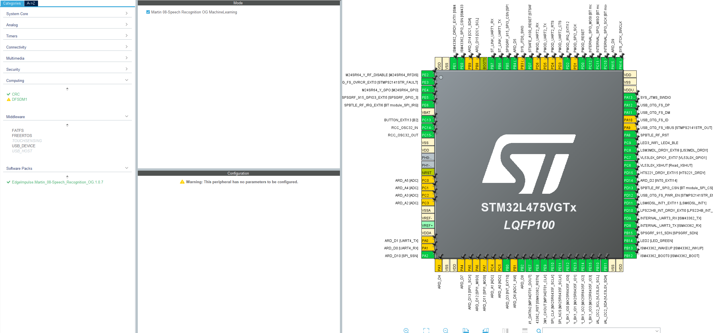
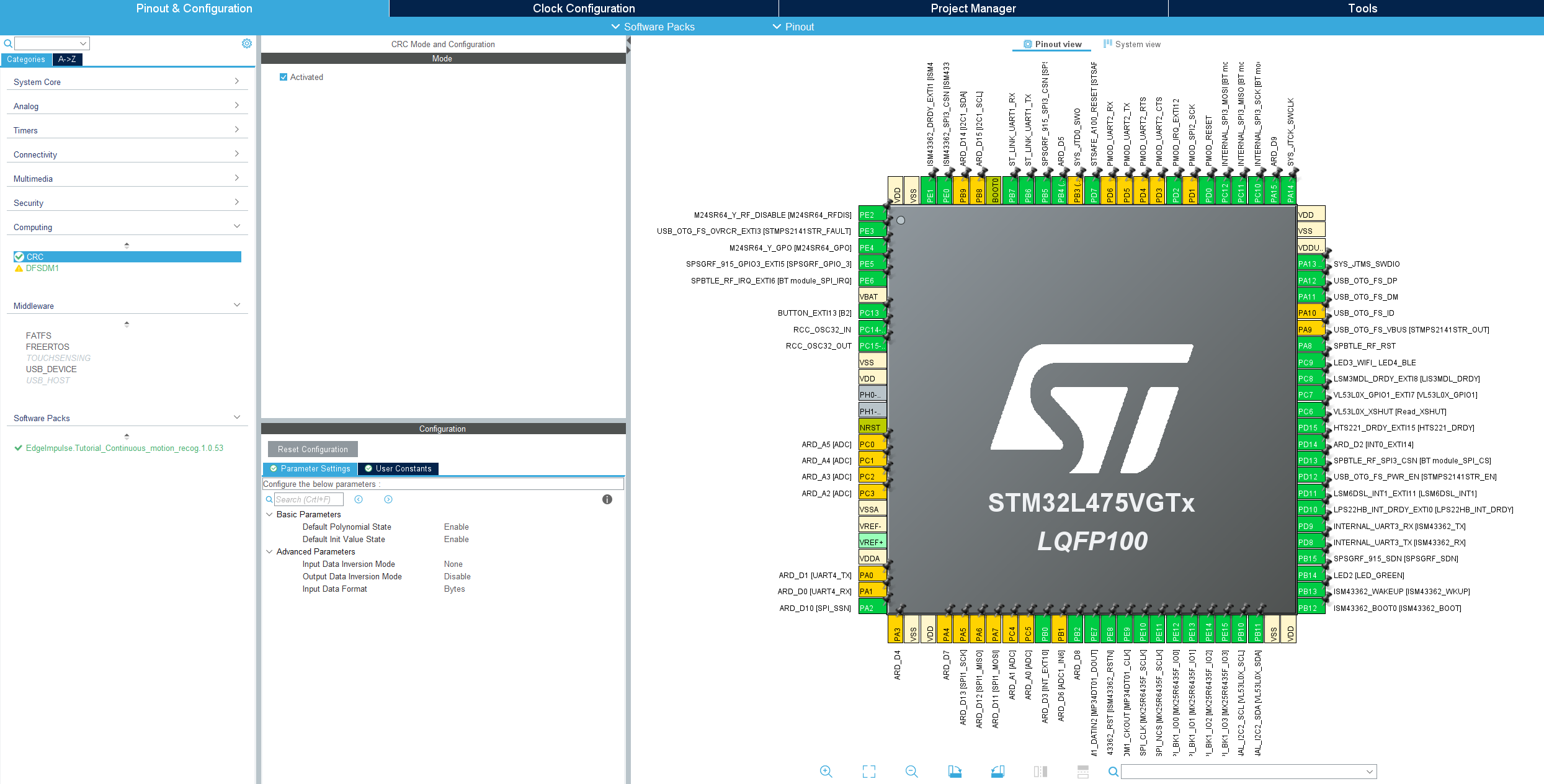
I think something went wrong in my model to begin with, when I initialized the IOC project, I had to manually initialize the UART1 ports, none of the other peripherals were selected. Given I’m using an official Dev Board, I found this unusual as normally I should get the option to at least initialize all pins in their default values.
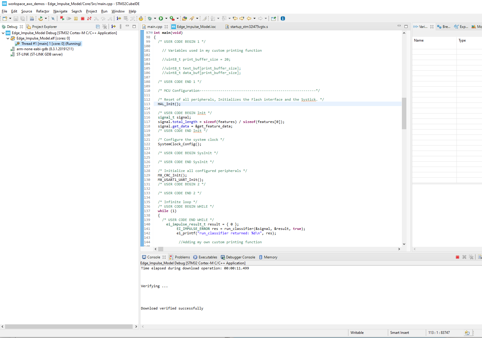
I can debug the code with no issues detected.
The Edge Impulse Client can detect the COM port which is connected to my board, however, none of the expected printing outputs are being outputted:
I’d upload the main.cpp file if I could. but it’s not an allowable file type.
Anyways, any help would be greatly appreciated 
@Martin_08 Can you print anything over the UART? E.g.
const char *msg = "Bleep, bloop, I'm a computer";
HAL_UART_Transmit(&huart1, (uint8_t*)msg, strlen(msg), 0xffffff);
Before you do anything with the model? Also is UART1 transmitting at baud rate 115,200?
Thanks for the reply,
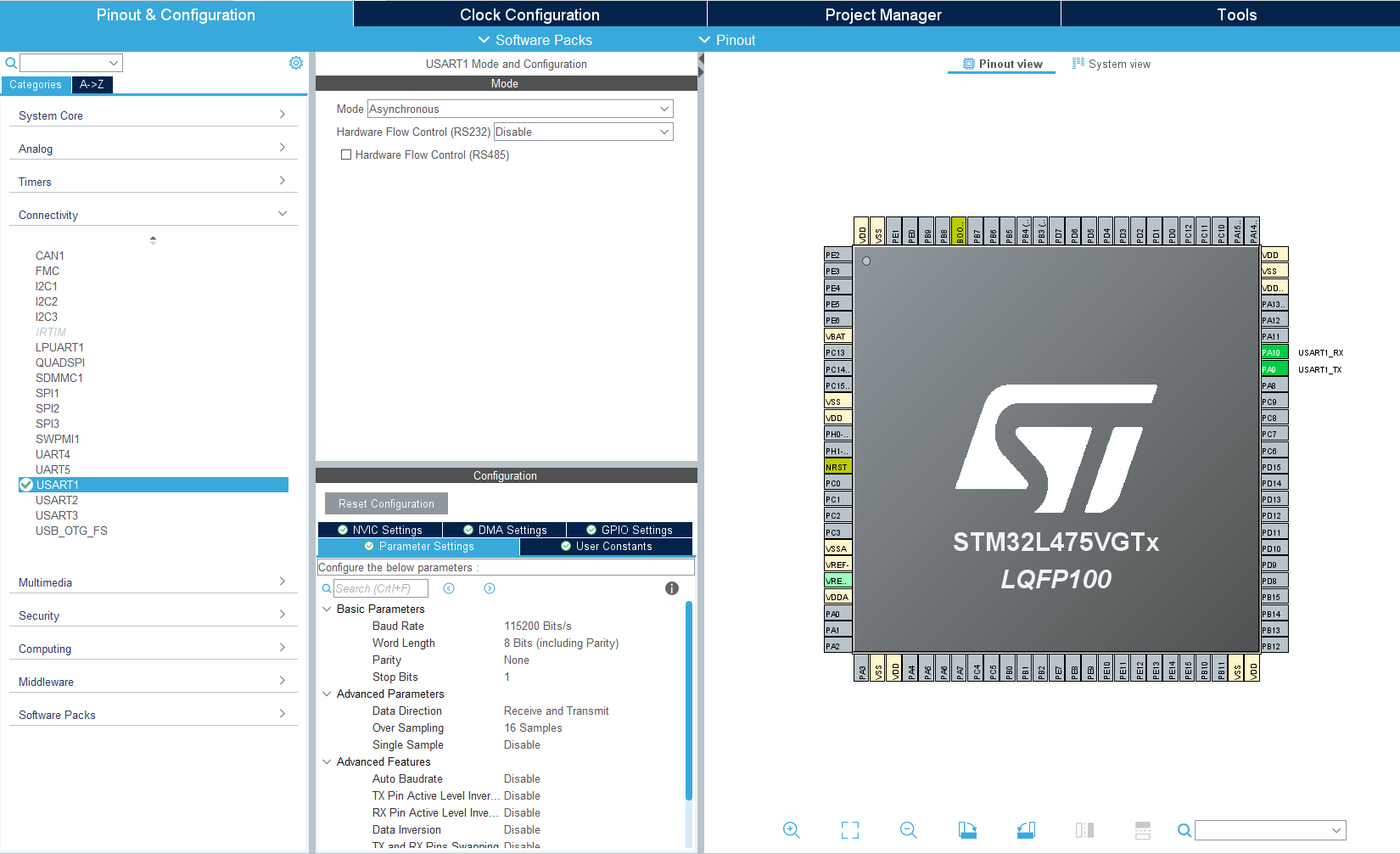
My USART1 is set with the following parameters:
I implemented that code that you suggested to see if I could print anything. Again, I can’t really read anything from Edge Impulse Client.
Could it be something related to all the pins in my IOC project being uninitialized except for USART1?
I suspect that at least some of the peripheral pins should have some sort of default configuration, but STM32Cube IDE didn’t actually give me an option to set all pins in the Development Board to default values.
I’d be more than happy to upload the main.cpp file if you can tell me how.
Thank you for helping me out with this btw, I would love to be able to use Edge Impulse in STM32 based devices
Hi @Martin_08,
When you initialize a project in STM32CubeIDE, what board did you select? I tried selecting the B-L475E-IOT01A1 and selected the option to initialize all the pins to their defaults for that board. It seems that it assigns many more pins than what you’re showing in your screenshot.
I don’t have that exact board, but from what I can gather, it seems that PB6 and PB7 should be used as the UART1 pins (as they are connected to the ST-LINK, which should give you USB-Serial translation). In your screenshot, you have PA9 and PA10 as your UART1 pins.
I recommend trying the default configuration for the dev board (that has most of the pins configured as shown in my screen shot) and see if that will run @janjongboom’s code snippet.
Hi Shawn,
Big fan of your work btw. You were right, I just had to create a new IOC project from scratch to get the option to start with the default pins.
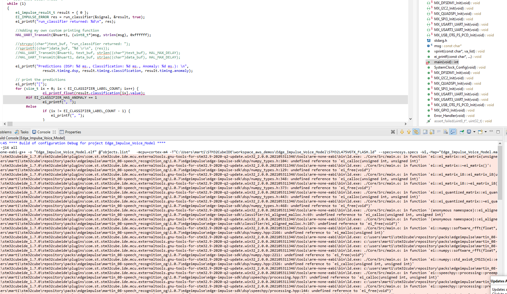
I have a new problem though, the C++ project cannot find the reference to the Edge Impulse model during my Debug Build. I’ve confirmed I’m working on a C++ project because it’ll only let me change it to a C project.
This is slightly weird because the main.cpp in my previous IOC code (the one which had no pins initialized) could build properly. I’ve added the same bits of code as the tutorial told me to.
Please help me Edge Impulse legends, you’re my only hope
Hi @Martin_08,
Thank you!
From what I can see in your error messages, it seems that the linker cannot find your Edge Impulse SDK library.
If you have not done so, I recommend reading through this guide to get an idea of exactly what header and source files need to be included in your project to get it to build.
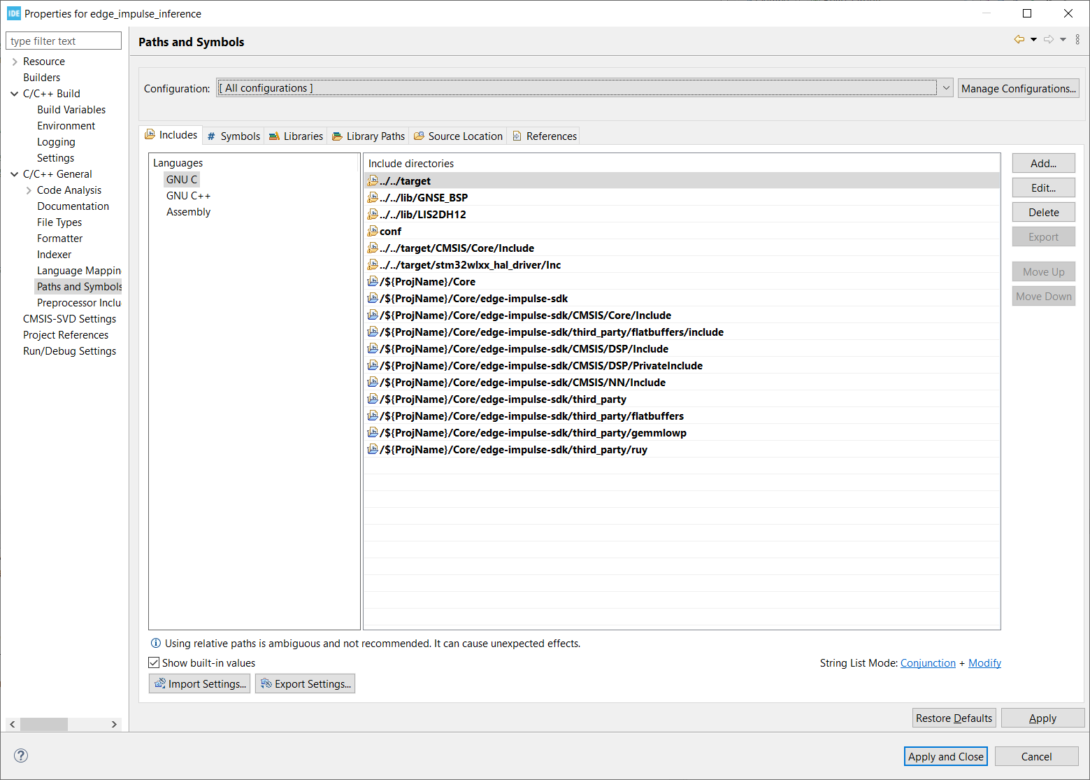
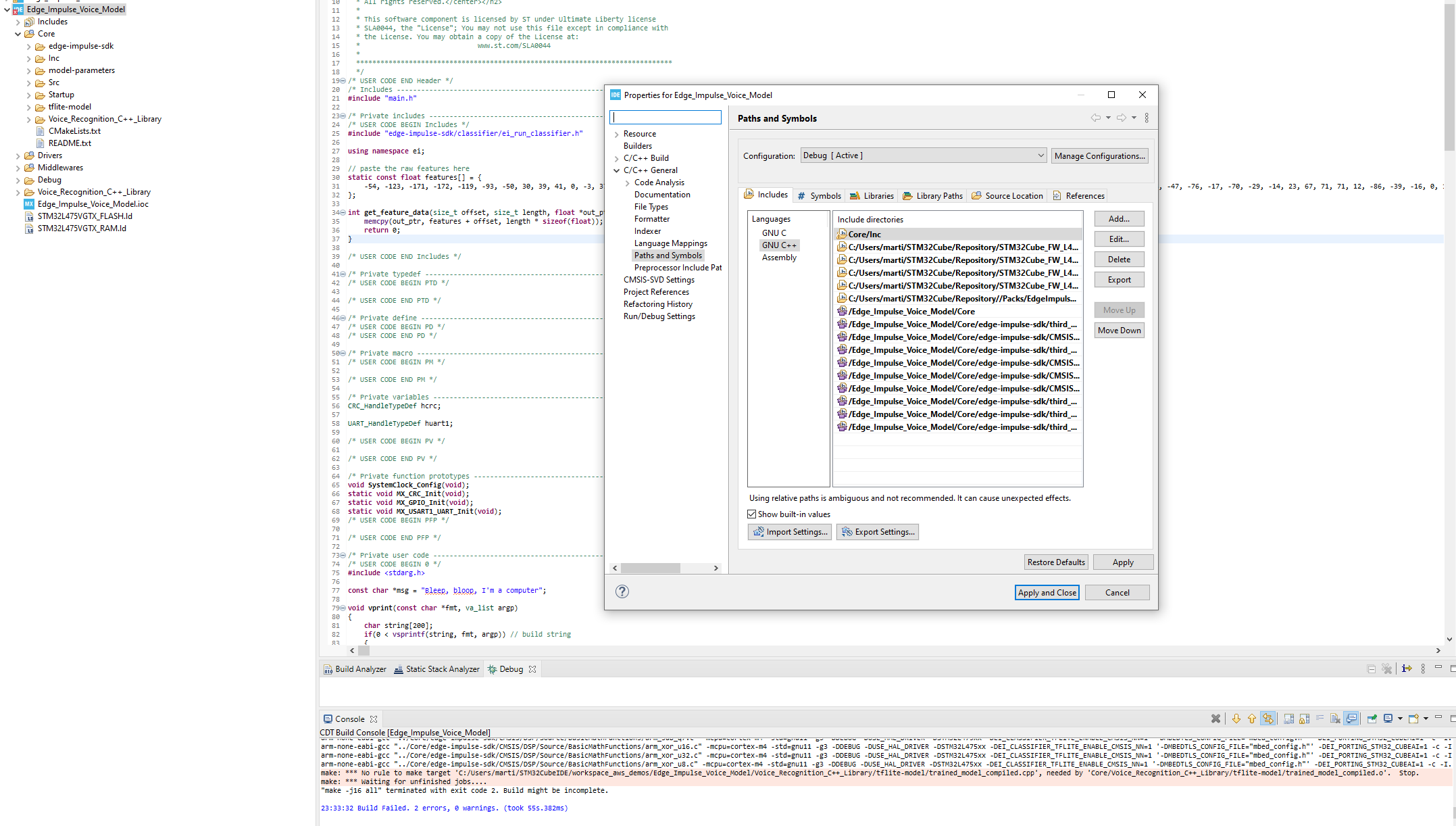
You will need to go into Project > Properties > C/C++ General > Paths and Symbols > Includes. Add the location of the required header files to GNU C and GNU C++ for both release and debug configurations.
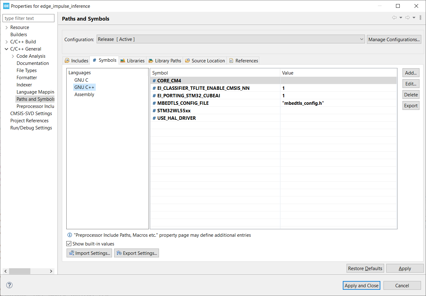
Go to Paths and Symbols and add the following symbols for the GNU C++ setting.
Eclipse should find the location of the source files automatically, but if not, you might have to go to the Source Location tab and tell it where to find the SDK source files.
If you find that everything compiles but you can’t print float values, you might have to add the compiler flag listed here.
Hi Shawn,
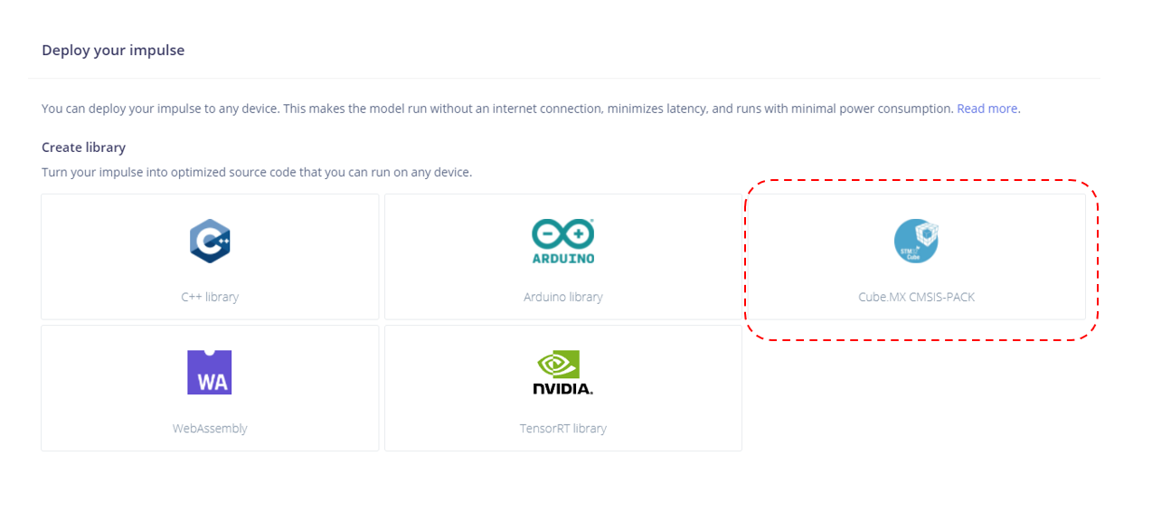
I really appreciate the help, but I think I’ve gotten really confused. My original understanding was that by using the CMSIS Pack option I wouldn’t need to download the C++ Libraries into the IDE.
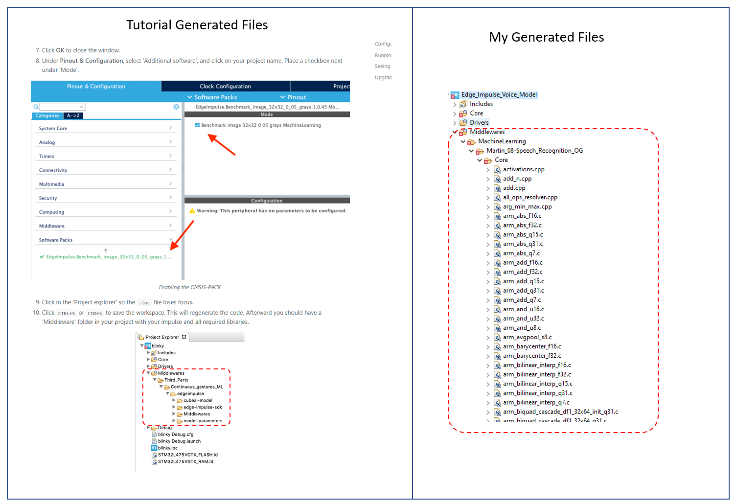
To add to my confusion, the tutorial’s version of the “Middleware” files which are generated from the CMSIS Pack seem to be different to the ones generated from my CMSIS pack. Why are the tutorial’s “Middleware” files already organized into folders?
Tutorial: https://docs.edgeimpulse.com/docs/using-cubeai#prerequisites
I thought I had added the CMSIS pack correctly:
Anyways, I have added the C++ library generated from Edge Impulse to the Core Folder as well, and added the C++ libraries to the Path Includes, and have copied the values you recommended for the Symbols. I’m still getting Build issues:
Again, I’m a complete noob in this space, the reason why I might seem to be rushing is because I don’t have permanent access to the dev board I’m using, so I wanted to do as much as I can while I have it.
Thanks again
Hi @Martin_08,
Ah! I apologize–I thought you were using the C++ SDK library rather than the CubeMX Pack.
You will need to remove the C++ library or start over again with a new .ioc project. I followed the directions in https://docs.edgeimpulse.com/docs/using-cubeai exactly and got it to compile (granted, I was using a simple motion classification project, so you may want to start there to see if it will work before moving to audio).
Make sure you do things in the very specific order as shown in that guide:
- Create new IOC project for your board
- Right-click on project > convert to C++ project
- Import downloaded Edge Impulse pack
- Save .ioc file, which will generate new code
- Rename main.c to main.cpp
- Copy in code snippets as shown in the tutorial
Let me know if that works!
1 Like
Hi Shawn,
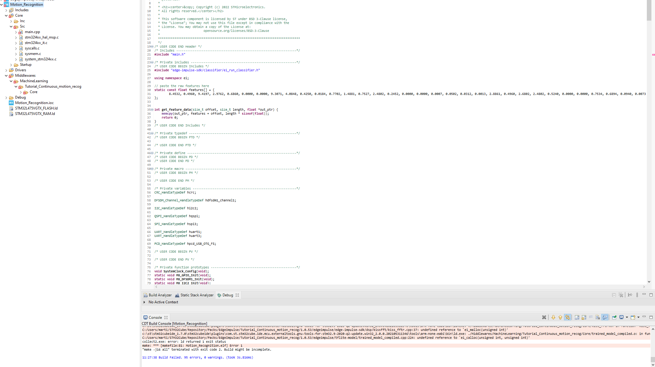
So I’m trying to use the Motion Recognition CMSIS Pack to try to find my original mistake.
I accessed the following public project: https://studio.edgeimpulse.com/studio/84984/deployment
From this project, I downloaded the CMSIS pack (after I cloned it) and went ahead and did the steps in the tutorial that you linked.
Again, I’m seeing that the folder structure in the Middleware folder is different compared to the tutorial. I’m not getting my files organized into “edge-impulse-sdk”, “model-parameters” and “tflite-model”, I’m just getting a bunch of C files in a Core folder.
I’m also uploading the IOC configuration I’ve used for this project:
I’m not really sure what to do.
Thank you for your continued support btw
Hi @Martin_08,
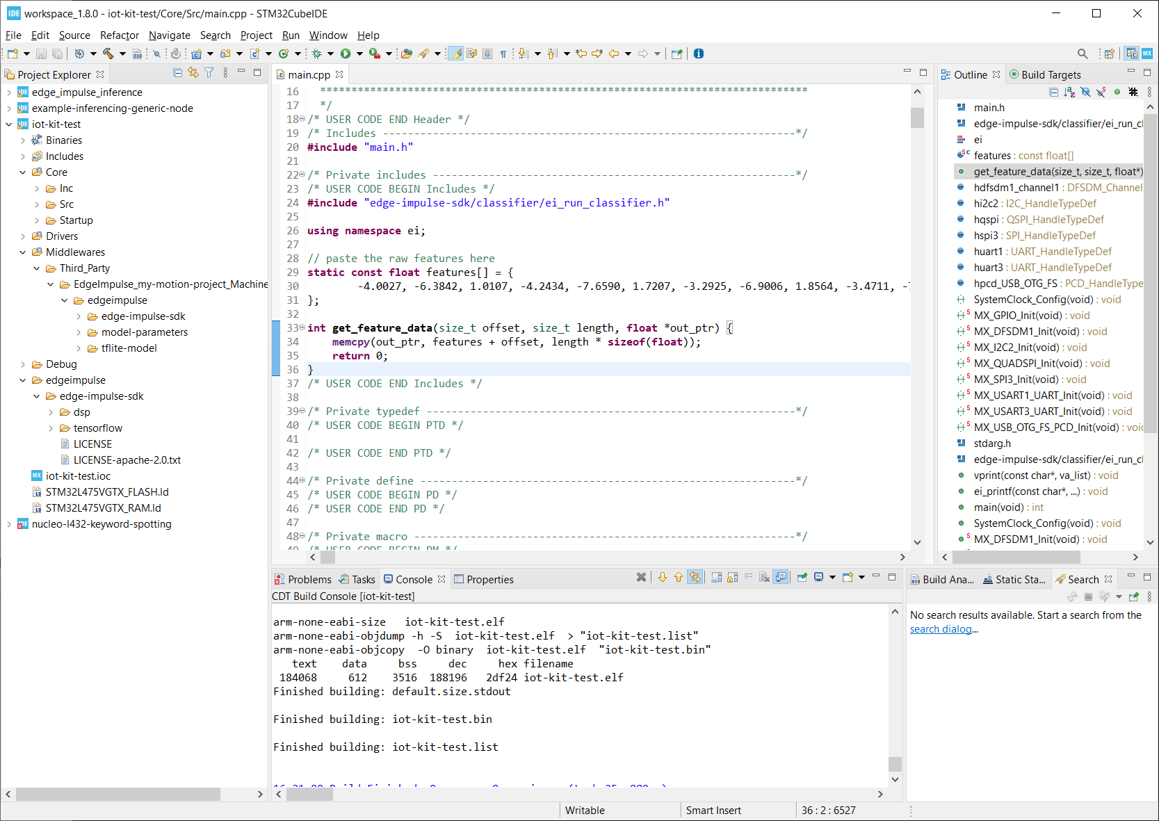
What version of STM32CubeIDE are you using? I tried the process again using v1.8.0, the tutorial project you linked, and the B-L475E-IOT01A1 as my board. The project still compiles for me:
Based on the error message I can see from your log, my guess is that something was not imported correctly, as the linker cannot find some of the Edge Impulse source code.
You’re a genius mate, I updated from version 1.7.0 of STM32Cube IDE to version 1.9.0 and it now compiles.
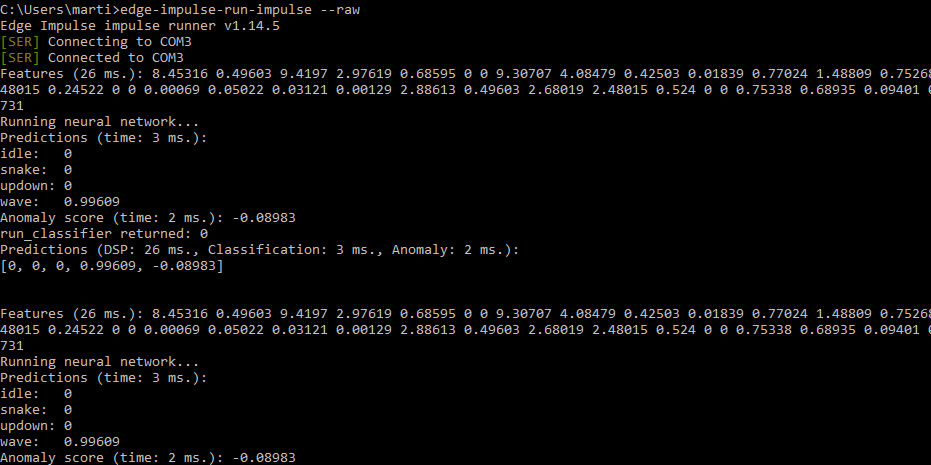
One more question though, my inference isn’t working the way I expected it to. The original features never get overwritten with the new feature values which are meant to be produced by the inference data, as a result, the prediction coefficients are always the same.
I have a feeling the answer to fix this latest part is trivial, but I would still appreciate it if you’d let me know how to modify the main.cpp script to successfully implement the real-time inference.
Thank you for your continued support.
Hi @Martin_08,
The tutorial has you copy features from a test sample into a static buffer. As a result, the buffer never changes. This allows you to test that inference works on your microcontroller without needing to connect a sensor.
To make it work in real time, you will need to make that buffer not ‘const’ (where X is the number of raw features per sample, which should be given be EI_CLASSIFIER_DSP_INPUT_FRAME_SIZE, such as 375 samples for 3-axis accelerometer data collected over 2 ms with 62.5 Hz sampling):
static float features[X];
Then, you would fill features[] with raw data from your sensor and call run_classifier() with it. While it’s not STM32, here is a description of what’s going on in a simple main example: https://docs.edgeimpulse.com/docs/deploy-your-model-as-a-c-library#create-an-application
It’s not fully continuous, as you’d want to collect data (e.g. 2 ms of motion data) then call run_classifier(). Because run_classifier() is blocking, you wouldn’t be collecting data during inference. However, I recommend starting there to get an understanding of how to fill a buffer and then perform inference.
Once you have that, you can switch to the run_classifier_continuous() function (which you can read about here: https://docs.edgeimpulse.com/reference/run_classifier_continuous). It becomes more complicated, as you need to fill a buffer while that function is running. This requires you to use something like DMA + hardware interrupts or an RTOS. You will also likely need to use a double buffer so that you don’t overwrite the first buffer while it’s being used for inference.
I have an example of using run_classifier_continuous() with audio data here: https://github.com/ShawnHymel/ei-keyword-spotting/blob/master/embedded-demos/stm32cubeide/nucleo-l476-keyword-spotting/Core/Src/main.cpp. Note that it’s quite old, so I can’t promise it will work. However, it should demonstrate how to set up DMA with hardware interrupts and fill a double buffer so that you can feed data to run_classifier_continuous() within your timing constraints to perform keyword spotting.
1 Like
Hi Shawn,
I seem to be having trouble with STM32 in general. I come from an Arduino hobbyist background and am used to having a lot of libraries to abstract a lot of the low level sensor interfacing.
As a result, I’ve been having trouble with interfacing with even the built-in sensors of my IoT Discovery Board (B-L475E-IOT01A). Are there tutorial videos or articles that you can recommend for:
This sounds like a really basic request, but I’ve found existing STM32 examples to be way too complicated to even understand how to use the IoT Discovery Board built-in sensors. I was under the impression that this board was made for beginners and it doesn’t seem the case so far 
BTW I love how you did your RTOS STM32 tutorial, that actually explained things quite well.
1 Like
Hi @Martin_08,
Moving to pure STM32 development from Arduino can be a big leap, as ST does not maintain libraries for individual sensors, motor drivers, etc. As a result, it is up to you to write the driver (e.g. with I2C) using their HAL, LL, or raw register read/writes. I am not aware of any articles that show you specifically how to do this with the LSM6DSL, so it will likely require reading the datasheet and creating the necessary SPI or I2C read/writes in C.
If you’d like to learn how to use HAL and LL with STM32, I highly recommend this book: Mastering STM32 book. You will want to set aside some time to go through most of it, up through the I2C and SPI chapters.
Alternatively, you could try PlatformIO, which will allow you to choose a supported framework, such as Arduino or mbed for that board (see the supported frameworks here: ST B-L475E-IOT01A Discovery kit — PlatformIO v5.2 documentation). By using a framework, you should be able to include libraries written by other people to make development easier.
Hope that helps!
Hi Shawn,
Your advice helped a lot, I learned how to use mbed and successfully ran the example from:
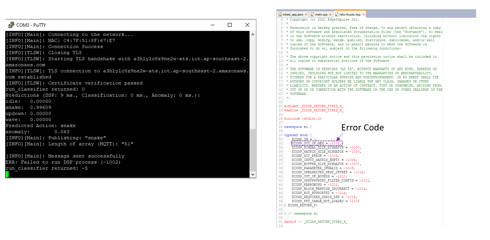
I’m now trying to make a new project which sends the motion recognition result to my AWS account, and this is where I’m running into trouble. I’m currently getting an error that is telling me (according to my interpretation of the error code) that my program is out of memory for the DSP operation:
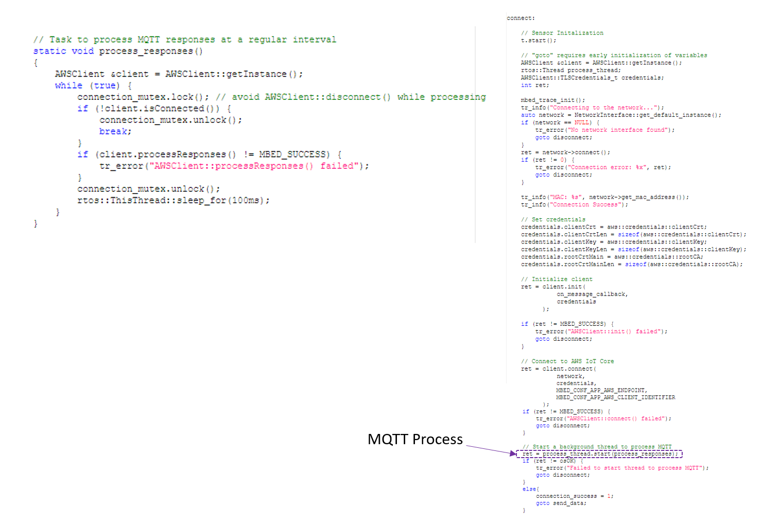
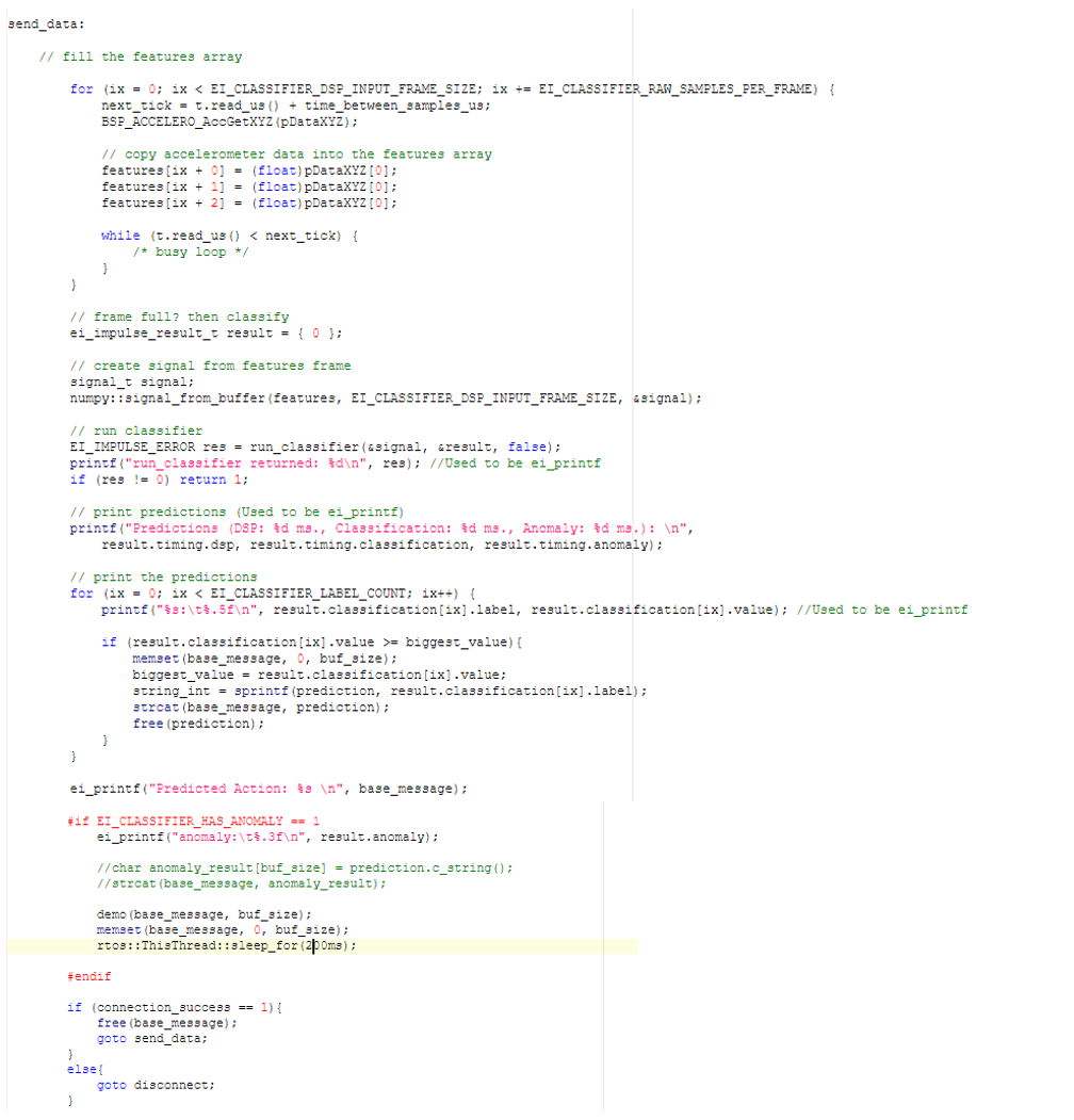
I admit that the way I implemented this in my code is very messy, basically I’m running an independent thread which is periodically processing the MQTT connection (I’m not sure why it’s needed, it was included in the original AWS mbed tutorial code):
At the same time I run my main loop which does the inferencing and motion recognition:
Originally I tried adding that RTOS thread delay (the line highlighted in yellow) to see if it would fix the problem (because I suspected that the MQTT process and my main loop were probably trying to access the same resources at the same time). I have to admit though, I’m a total noob to RTOS and resource allocation, and I mainly included this RTOS thread delay because it was present in the original Amazon mbed example.
Anyways, this is mostly a “hail mary” to see if you could give me a hint as to what I should do to make this work.
A huge thank you in advance.
Hi @Martin_08,
When you create a new thread, it will automatically allocate a chunk of RAM (usually from the heap) to use for task management and creates a separate stack for variables in the thread. I’m not too familiar with MQTT, but my guess is that the it (along with whatever networking library you’re using) require a good amount of RAM.
The run_classifier() function will automatically allocate and deallocate memory from RAM as needed. It sounds like your MQTT+networking functions are already using a good amount of RAM, so when you call run_classifier(), it fails trying to allocate more RAM than what’s available.
There are a few options:
- Get a microcontroller with more RAM
- Use a separate microcontroller: one for inference and one for networking/MQTT
- Reduce the size/window of your data collection to use less RAM (this may mean reducing accuracy)
- Do everything serially in a superloop so you don’t allocate networking and inference memory at the same time: sample from sensor(s) → inference → boot up networking → use MQTT to post data → disable networking to deallocate memory.
Hope that helps!