Hi Edge Impulse Team,
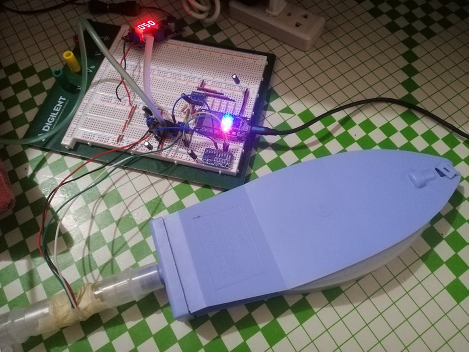
I’m aiming to classify ventilator waveforms in near real time. As shown in the picture, I’m using an ESP32 with flow (SFM3300) and pressure (MPX5010DP) sensors.
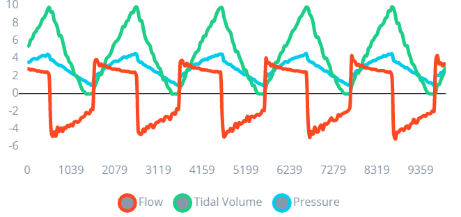
I’m using a data forwarder to record three metrics at 50 Hz: flow, volume, and pressure. The dataset was made up of eight (8) labels, each lasting 10 minutes. The waveform graph example is presented below.
The following settings for the Impulse Design are shown below.
Window size: 1500 ms
Window Increase: 250 ms
Features Extraction: Spectral Analysis
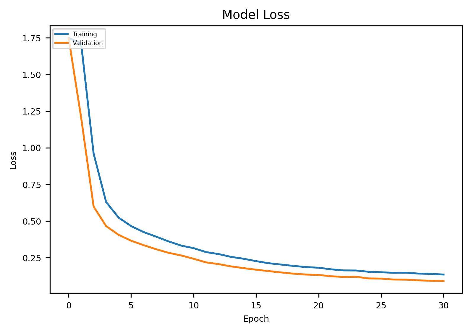
The results of the neural network once it has been configured are provided below.
Training
Model Loss
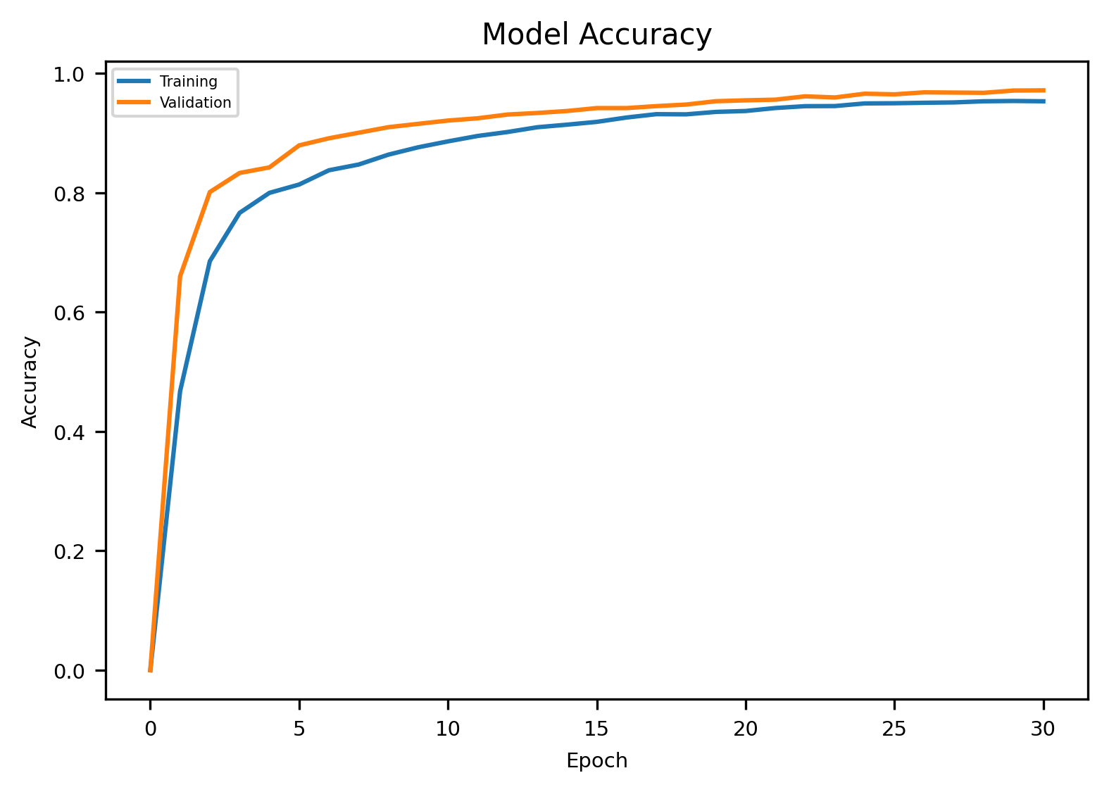
Model Accuracy
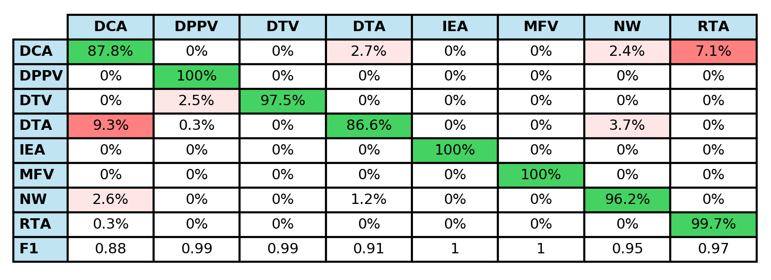
Confusion Matrix
Validation
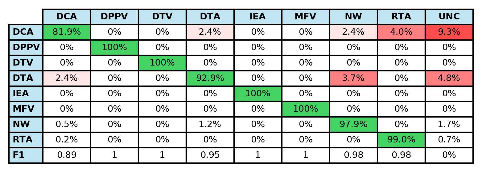
Testing
The model appears to fit and perform well in the live classification. However, when the model is run on hardware, it fails to categorize the ventilator waveform, data from sensors.
Below is a sample sketch.
void loop() {
unsigned int rawData = sensirionFlow.getValue();
…
// Features buffer full? Then classify!
if (feature_ix == EI_CLASSIFIER_DSP_INPUT_FRAME_SIZE) {
ei_impulse_result_t result;// Create signal from features frame
signal_t signal;
numpy::signal_from_buffer(features, EI_CLASSIFIER_DSP_INPUT_FRAME_SIZE, &signal);// Run classifier
EI_IMPULSE_ERROR res = run_classifier(&signal, &result, false);
if (res != 0) return;Serial.print(F("Predictions (DSP: “));
Serial.print(result.timing.dsp);
Serial.print(F(” ms., Classification: “));
Serial.print(result.timing.classification);
Serial.print(F(” ms., Anomaly: "));
Serial.print(result.timing.anomaly);
Serial.print(“ms.): \n”);// Print the predictions
for (size_t ix = 0; ix < EI_CLASSIFIER_LABEL_COUNT; ix++) {
Serial.print(result.classification[ix].label);
Serial.print(F(":\t"));
Serial.print(result.classification[ix].value);
Serial.print(F("\n"));
}#if EI_CLASSIFIER_HAS_ANOMALY == 1
Serial.print(F(“anomaly:\t”));
Serial.print(result.anomaly);
Serial.print(F("\n"));
#endif// Reset features frame
feature_ix = 0;
}
}void TaskPlot(void *pvParameters)
{
(void) pvParameters;
TickType_t xLastWakeTime;
const TickType_t xFrequency = FREQUENCY_HZ;
xLastWakeTime = xTaskGetTickCount ();
for (;
{
// Scaled and filtered the waveform for plotting
filteredFlow = flowFilter.get() - 0.00;
scaledVol = tidalVolume / 25;
filteredPres = pressureFilter.get() - 1.02F;// Fill the features buffer
features[feature_ix++] = filteredFlow;
features[feature_ix++] = scaledVol;
features[feature_ix++] = filteredPres;vTaskDelayUntil( &xLastWakeTime, xFrequency );
//vTaskDelay(INTERVAL_MS / portTICK_PERIOD_MS);
}
}

Is the model underfit / overfit? or there are any adjustment or recommendation for this one? Thank you so much for your response.

