Just out is the Arduino Portenta Vision Shield with LoRaWan connectivity.
https://store.arduino.cc/usa/portenta-vision-shield-lora
Basically it is the same as the Ethernet Vision Shield with camera, microphones, ethernet and jTAG, but changing Ethernet to LoRAWan.
Anyone on the forum familiar with LoRA? I am very interested in connecting multiple Arduinos using both I2C and LoRa, but am a bit of a newbie. Anyone with experience with a Gateway. I have been looking at the Draguino
Not many Gateways in Canada so also looking into peer-to-peer, wondering if anyone has used a LoRa module that would work on the Nano33BleSense?
@Rocksetta, in case you hadn’t seen it: https://github.com/edgeimpulse/example-portenta-lorawan => Portenta + LoRaWAN + Edge Impulse.
Regarding connecting a LoRa radio to the Nano 33 BLE Sense, there are two options:
- Connect a radio (SX1261, SX1262, SX1272 or SX1276) directly, but this requires driving the radio stack on the Nano 33 BLE Sense. This should theoretically be doable, as The Nano 33 BLE Sense runs Mbed OS underneath which has a LoRaWAN stack, but probably not an easy route forward.
- Use a module, which is what’s done on the MKR WAN 1300 and the Portenta Vision shield. I think it’s the Murata CMWX1ZZABZ-078 on both of them, and that works with the
MKRWAN Arduino library. But I guess any module will work similar.
FYI, these gateways go for 69$ and work well for experimentation: https://www.thethingsnetwork.org/docs/gateways/thethingsindoor/
2 Likes
That Gateway is the best for the price I have seen. Thanks for the link. Trying to figure out if I need an Antenna with the Portenta LoRa Vision Shield. It looks like the same connector as for a wifi or BLE antenna.
As LoRa is not fairly big in Canada at the moment I am hoping I can use the shield to do some peer-to-peer LoRA. Anyone any opinion if the Arduino library will allow peer-to peer?
I’m using it without an antenna and it’s fine - but I’m 4 meters away from a gateway 
No experience on p2p unfortunately.
1 Like
I think this is the correct antenna, it has the micro uFl connector and is not that expensive. Dipole Antenna for Arduino
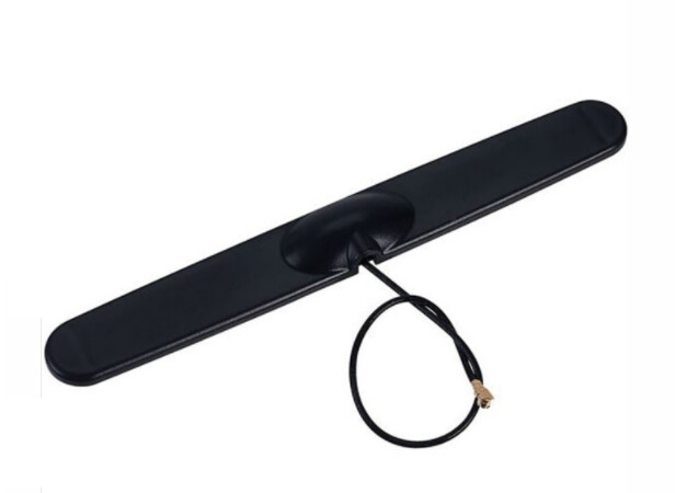
Doesn’t look like the other LoRA antenna’s
I just asked this at the Portenta Facebook site at
I have no low power estimates for running the “always on” vision shield camera and https://openmv.io/ or https://www.edgeimpulse.com/ software and a daily LoRa upload. Anyone try guessing at how many AA batteries would be needed to keep this thing running for a month? (I realize that would depend on the actual program), but would be interesting to know if 4 AA batteries can keep it going for a week, or a year?
Like most of what I do, if anyone actually knows what they are talking about step right in.
Here is a chart by http://techlib.com/reference/batteries.html which is a good starting point although Wiki might be
a bit better
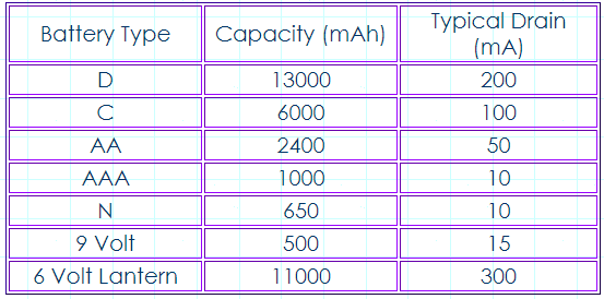
Putting AA batteries in Series keeps the same capacity increases the voltage but in parallel doubles the capacity with the same voltage so 4 AA batteries in series and parallel would give us 3V and 2400x2 = 4800 mAh.
Next the current pull from the PortentaH7 with Vision shield running an OpenMv or Arduino based Machine learning program.
This online calculator can help https://www.omnicalculator.com/other/battery-life
I typically like really life experiments where I hook up fresh batteries and just let them run until the Arduino stops, but
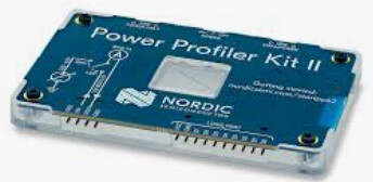
most of us Edge Impulse Ambassadors have the Power Profiler II.
All we need to do is figure out the power drain during a classification and the power drain during sleep and then how much time in either mode.
Unfortunately I don’t know how to use the Power profiler. So I guess it is time to learn.
Here is a link https://www.nordicsemi.com/Software-and-tools/Development-Tools/Power-Profiler-Kit-2
Anyone got the quick steps on how to use it with the Arduino PortentaH7?
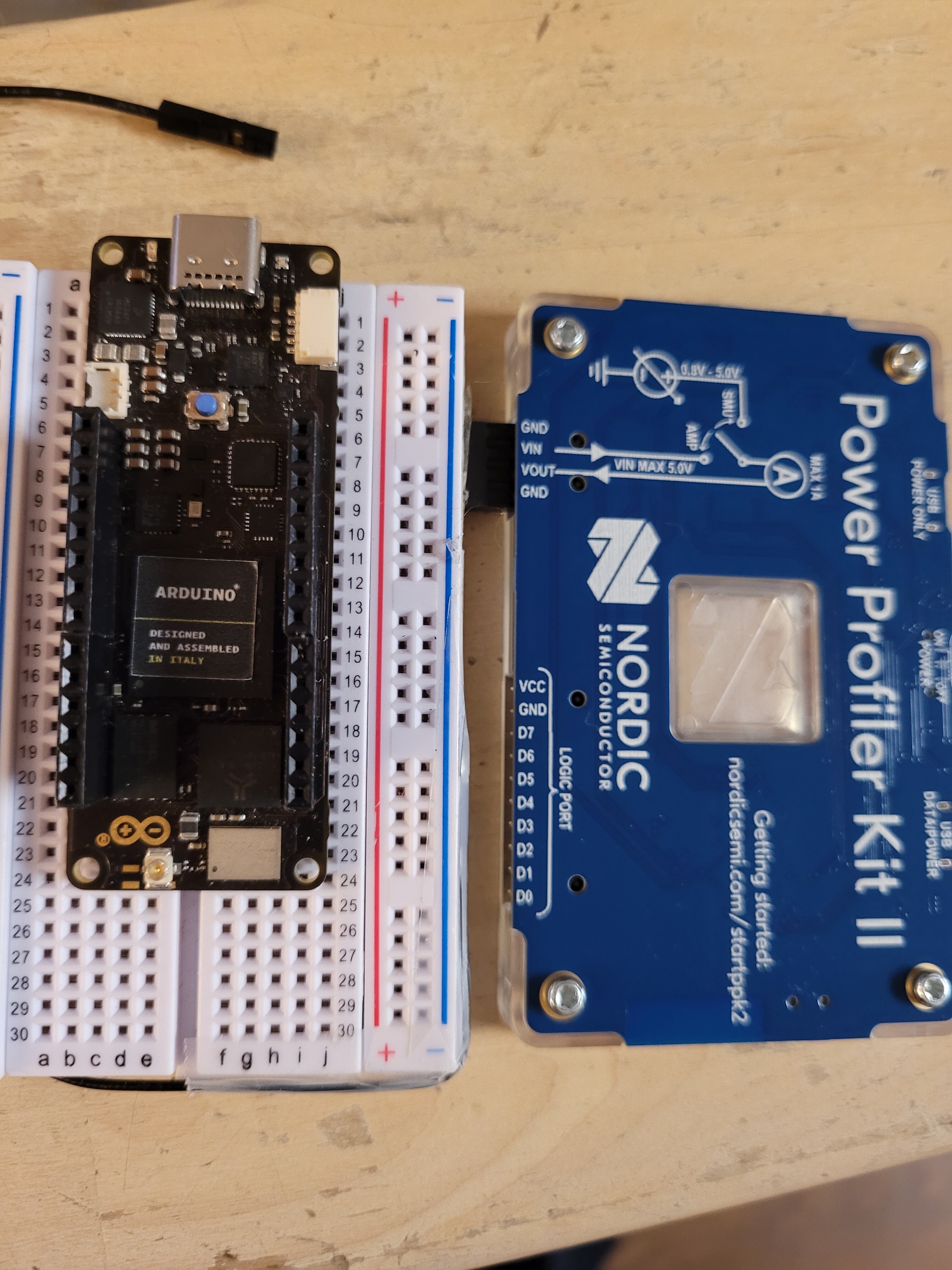
So I kind of understand the operation of the PPK2 (Nordic Power Profiler II) but I am a little unsure of the connections to the Portenta (nervous about connecting it incorrectly)
I am thinking to connect:
PPK2 GND to Portenta GND
PPK2 VOUT to Portenta VIN
PPK2 VIN to Portenta 3V3 or 5V?
And is that it? Any opinions?
Little add-on here, since the portenta is ready for a LiPo battery probably should do the calculations for a 3.7V LiPo. The small ones seem to be between about 500mAh to 6000 mAh)
You should only need two pins, external power => VIN, GND => GND. However, I’ve just hooked the Portenta up to my Otii Arc (https://www.qoitech.com) and I don’t see the device powering up at 3.3V. Maybe it needs 3.7 at least? Or a jumper or something to get power from Vin (like many ST dev boards), but there’s no jumpers that I can see 
edit: Asked Arduino, and Vin should be 5V. Not sure if the profiler kit can supply that?
I think in source mode it can range up to 5V. I will check.
The PPK2 has an impressive startup, green flashing box, then bright red, then back to green. The profiller will do 5V
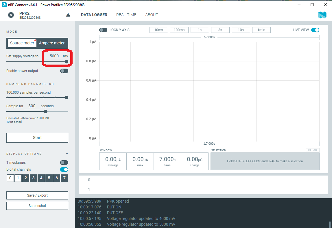
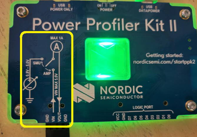
This is the circuit diagram that confuses me.
Vout from the PPK2 to the Portenta Vin on 5Volts does make a quick blip of both main LED’s, but that is it. Any other voltage has no results and when I run the data collection no LED’s. I think the Vin on the ppk2 is the issue, just not sure what to connect it to.
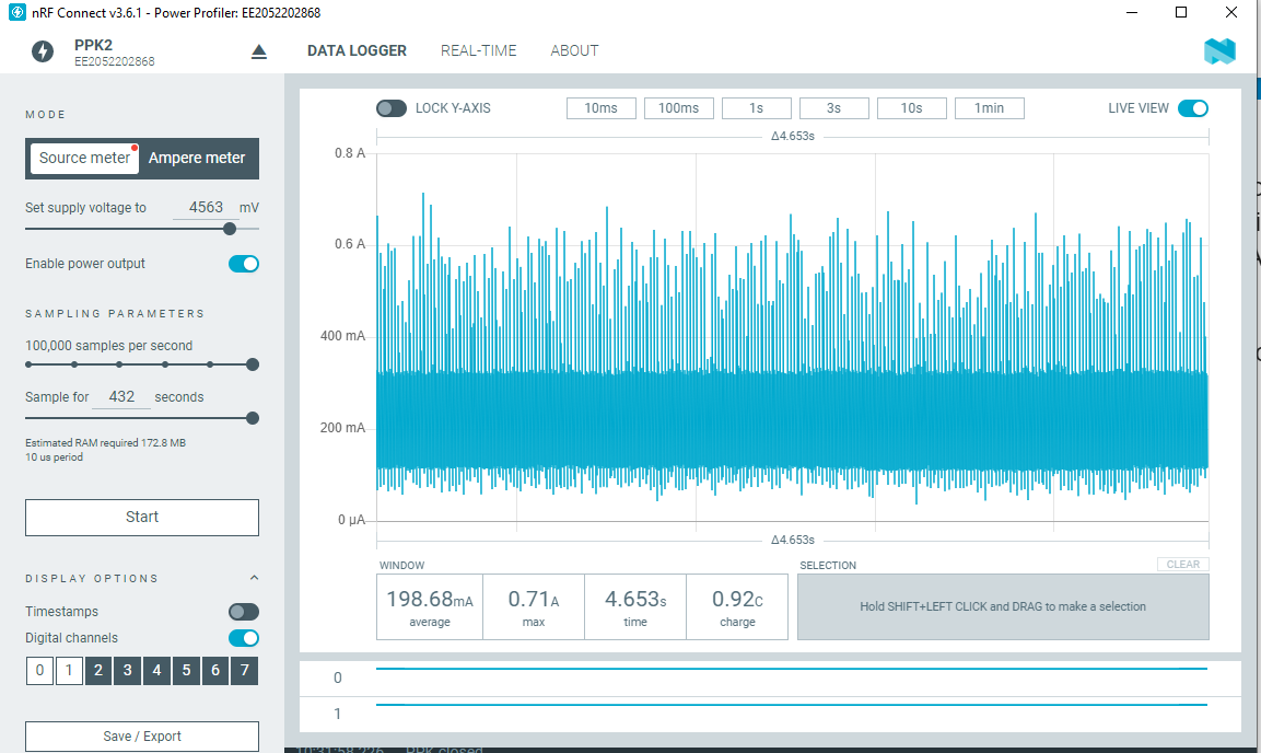
LOL, part of the issue was my fault. I had a program on the Portenta that just blipped the LED’s briefly. But now with a sensible LED switching program, still not getting much useful information with just the 2 connections. At least I now know the lowest working power is 4.56 V (4560 mV).
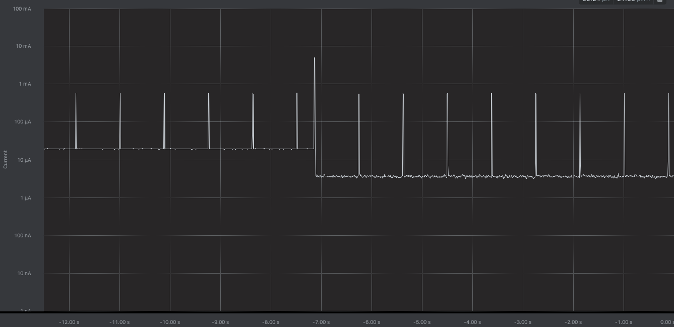
Graph is not very useful as I still think an extra connection is needed. I have an LED lighting 3 times near the end of the graph. And these numbers are really big. ~200 mA average. Ouch.
I will have to dig around for a LiPo connexctor. I assume that connector would power the Portenta with 3.7 V.
Anyone any ideas of other connectors to try. I did briefly connect the Portenta 3.3V to PPK2 Vin, but the graph was worse than below.
Here’s a thought. When working with the Potenta with the DAC pin, it was useless unless the AREF pin was connected. Could that be the mysterious unknow pin? Also why does the PPK2 have 2 ground pins?
If you see 200mA base it looks like it’s never going to sleep. I think pinging the people in the Arduino forum (or the https://github.com/arduino/ArduinoCore-mbed repository) will probably yield a faster response.
1 Like
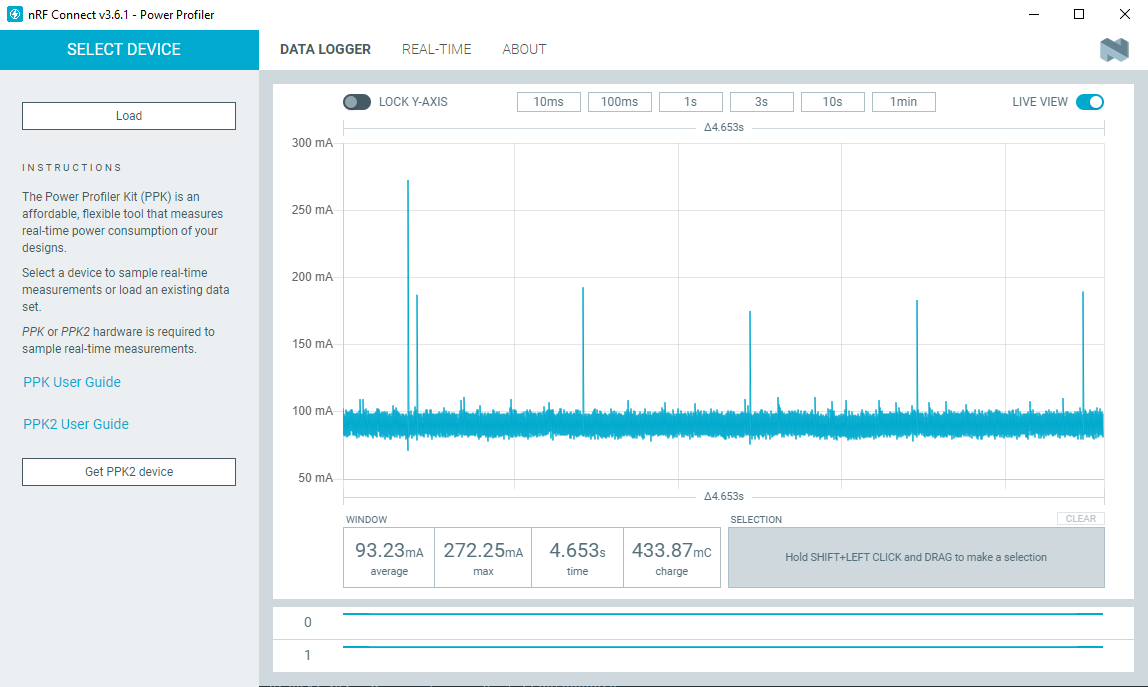
Looks like @janjongboom connection idea is correct. Here is the graph from a little WiFi board I teach with running the same simple blink program
.
and here is the Portenta Graph same connections same blink program
.
.
I still think I have done something wrong and still need to figure out how to activate sleep mode but this was interesting.
So other Mbed targets should automatically go to sleep when you call delay() actually, I’d recommend asking a question at the ArduinoCore-mbed repo and see if they know what’s preventing sleep.
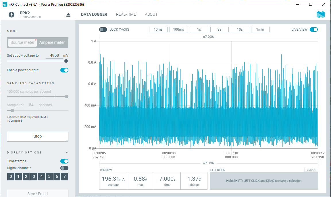
Here are some of my results.
Running the new Arduino Camera library and an Edge Impulse model with the Portenta Ethernet Vision Shield
.
.
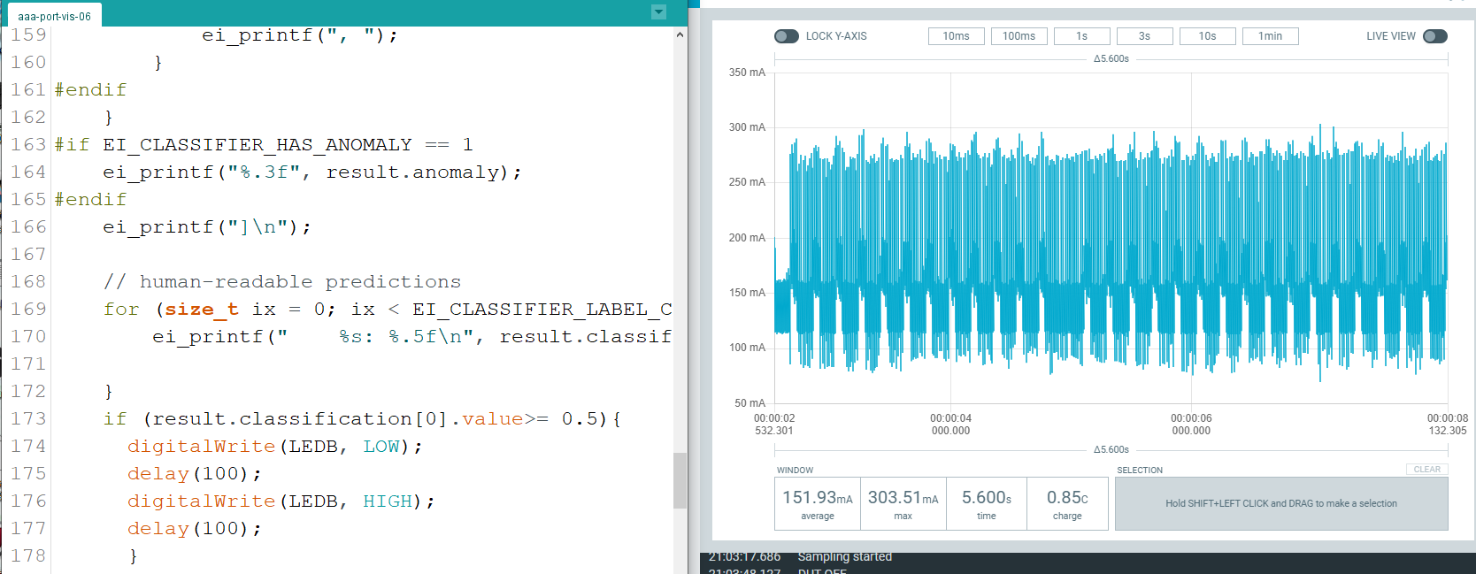
Strangely just using delay and the onboard LED I get a similar graph with the portenta
.
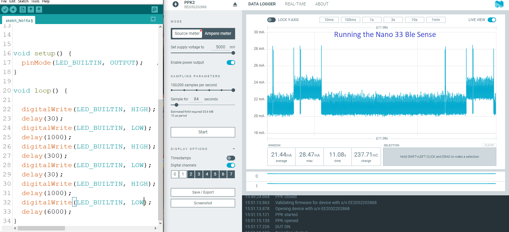
To compare:
Whereas the Nano33BleSense using the onboard LED looks like what I would expect
I have talked to Arduino and they seem a bit concerned about the results. If the Nano didn’t look so much better I would think I messed up somehow. Curious how other boards are with their baseline power consumption.
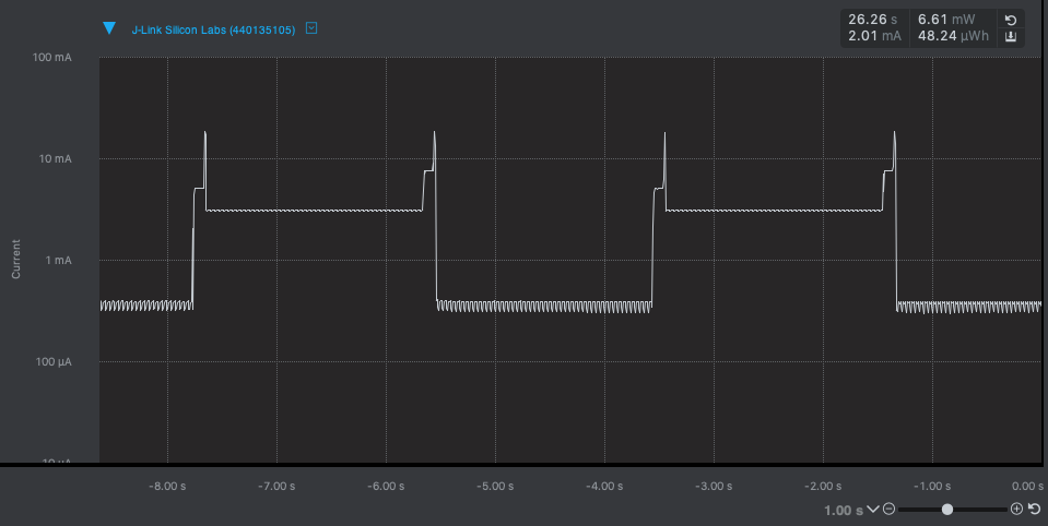
The Nano 33 BLE Sense looks too high for me as well. E.g. this is LED on on a Nucleo board that properly goes to sleep.
Or a low-power part with the systick running:
1 Like