The Edge Impulse examples I have seen so far seem to either use a single sensor or (like a video camera) detect a pattern within a single frame.
I have an array of ir sensors that I read into an ESP32 at a frame rate of ~30hz across an SPI daisy-chain. Each sensor has a reflective ir detector giving me a reflected amplitude value at each position.
What I would like to do is to detect and categorize hand movement across the array (up/down, in/out etc) which means finding patterns that run across each frame in time. Is this doable with Edge Impulse?
I am happy to get onto the learning curve but would appreciate some views/guidance, before getting deeply into it, as to the practicality of this application. Hoping that someone ahead of me on the curve might be able to comment.
Am I correct to assume the array is arranged as a grid? If yes then this becomes a image detection problem as you could treat each sensor as a pixel. You could then try to build a gesture detector to classify movement (the experts need to advise here)
It will be a very low resolution probably grayscale (if I understand you are measuring analog intensity based on reflection?) otherwise a 1bit image black and white(on or off only).
If you want to use the standard image training workflow I am guessing you would need to get the data from your own raw pixel values into an image data data format for training purposes as a somewhat naive approach. With inference you would then need to create some code on the ESP32 to read the data from the array as though it were an image sensor i.e. create a driver for your own custom image array.
Looking at this guide https://docs.edgeimpulse.com/docs/image-classification, specifically paragraph 2 of section 3, a more robust approach might be to bypass the image processing block and build feature arrays from the raw data and either save and upload or stream directly to the ingestion backend for training by the transfer learning block. For inference you could run locally off these features provided you pass them into the inference engine in a format that matches the features that were used to train.
Pete, thank you for your full reply. I was thinking the sensor array could be treated as an image albeit of very low resolution (typically 64 sensors) and I see there is already documented example of how to transfer learning data out of an ESP32, though for the moment I cannot find it again.
The problem I am trying to get my mind around though is that I am not really forming an image. What I have is, in effect, one illuminated pixel in each frame (or maybe a few clustered) and by combining the pixels across multiple frames I am looking to give the pixel/cluster a 3D Velocity. So do I have a two stage problem: recognize a cluster; determine it’s velocity across multiple frames. The latter being akin to gesture recognition but across multiple sensors.
So I think my question is about whether it is possible/practical to use Edge Impulse to recognize a gesture across multiple sensors and multiple images.
Pleasure hope I could help in some way. So based on what you say I am guessing your application has the sensors widely spaced (you say only one illuminated pixel per frame).
You also mentioned they are reflective IR sensors, do you actually mean diffuse sensors where you have the target reflect light back to the sensor as opposed to one that has a reflective mirror on the other side? I am being pendantic here about the terminology but I am guessing you are going for a diffuse sensing mode as thats the only way you can obtain an analog signal back because a reflective mirror sensor will only give you presence or no presence. Again I am assuming you are building something custom here and probably using IR sensor devkits but the principle of diffuse sensing still applies and one thing you need to keep in mind is background suppression.
By background suppression I mean movement behind the hand or whatever you are detecting or if you move the jig around to point at different colour surfaces it will throw off your readings due to background variation. Remember the sensor picks up whatever is in front of it even when your hand isnt there depending on its working distance of course Just think about that and try to visualize it.
As with all things analog that introduces a “noise” into the equation. Unless you have taken that into account already and the array is always facing a controlled environment if you get what I mean. Also besides this interference you will also have to deal with good old fashioned noise sources inherent the electronics and depending on the resolution you want to achieve this may may or may not be an issue.
Coming back to your setup, using the array as the frame of reference looking along the axis that the sensor array sees as the Z axis will your coordinate system entail x/y being the up down movement across the array and the Z axis being the analog sensor reading?
You could get away with the x/y system to give 2D movement without using ML. Off the top of my head I would approach this by creating a datatype that is based on multiples of the a type size say 8bits or 32 bits depending on the MCU you are using (so that you can expand your array and that its portable). Then create functions to deal with whatever size array you created and treat it as one long continuous buffer so in your case 64 bits would be needed so this could be 2 x 32bit words or 8 x 8bit words which you can then “stitch together” to one one 64bit word in your functions for this specific case.
If you are only going to have one bit active at a time you could detect movement in the x direction using the fact that a single bit shift is either multiply by 2 or divide by 2 and for y movement you could detecting whether or not the number changes by a rows worth of pixels. For speed you could do what essentially basic differentiation (delta x/delta t) etc but you need to make sure these calculations are are blocking and cannot be preempted otherwise it will throw your timing off and mess up your velocity calculations.
The above approach will have problems when more than one pixel is active so this could therefore be better solved perhaps with ML using a regression approach to output the metrics rather than the basic approach above as ML will assist with the non consistencies in the environment (here the ML gods need to advise).
Finally the Z axis being analog in nature means you need to take some measurement of noise background etc either and do filtering etc etc or even better I would recommend a Time of Flight Sensor that does accurate measurement (way better than you can do with IR sensors) and with a digital output all the analog front end and DSP stuff is baked into the chip and the vendor has spent the time perfecting this. I have personally played with (not yet used in a project) the ones from ST and they are quite good and cheap and all usual sources have ready made boards with them mounted. There are others though too.
I hope that can help in some way the ML experts will be better placed to advise on what way to tackle this using ML. Sounds like an interesting project.
@hundred1906. Adding to an excellent explanation by @pete . So what I’m assuming right now, is that you have 64 IR Sensor data axis, being fed into the ESP 32 board. What you could do is use each IR Sensor data as an individual axis, and feed the corresponding distance vs time data to the EdgeImpulse Studio. Now, since there are 64 sensors, this would be a large amount of data for each sample, but this would make the gesture sensing more robust, allowing you to include multiple types of gesture.
This works similar to how Accelerometer data is captured, except there are 64 axis distance vs time samples being recorded. Ensure that the data being collected by each sensor is in proper position so that the data accumulated records the corresponing gesture. Now, you could use the DataForwarder to collect the data from the sensors onto the Studio - https://docs.edgeimpulse.com/docs/cli-data-forwarder
With this, the data being collected will show up as 64 axis.
Make sure you don’t overfit the model. You have 64 axis of data for the model to normalize, pool down and train. So ensure that the sliding window size isn’t too short, or there aren’t too many iterations. Ensure that you have sufficient data per label.
I’m not sure if I have understood your question very well, but I was trying to put forward a simpler approach to your use case. This was a small addition to the detailed exaplantion put forward by @pete!
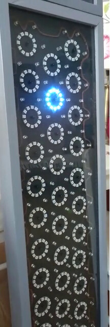
It’s great pete and dhruvsheth that you have put so much time into my question, especially when I have not fully described the application. That’s not because it’s a great secret but because I wanted to try keeping the question simple and focused. The original idea was not mine but I have adapted it several times so that it is now modular, scalable and easier to assemble. With any luck a picture of the second iteration prototype should be attached and on that you can see the ir illuminators and detectors.
pete discusses the problem of background suppression which is a problem. I do this at present by using a combination of taking measurement with and without ir illumination and by using a nearest neighbor suppression method. It works passably but I am changing the sensor to make use of the ltr-559 integrated sensor which is both cheaper and less sensitive to background radiation. I have tried various time of flight sensors and they are great, perfect even, except for the cost which I have to multiply up by 64/128 or whatever, depending on the number I need to usefully interpolate hand position.
dhruvsheth is way ahead of me in describing an ‘axis’ and in describing a ‘proper position’. I think you are saying format the frame data so that all cells are represented and each has a position and an amplitude.
But what I am picking up here is that the application is potentially solvable using Edge Impulse so that it is worth getting onto the learning curve. Thank you for that.