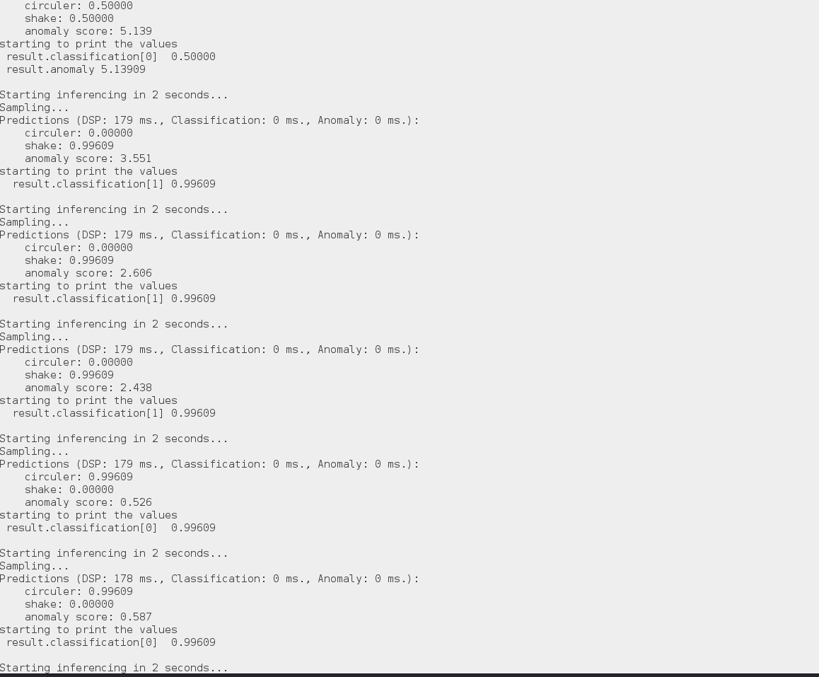
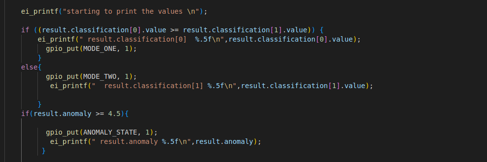
thanks for the reply Shawn. before I decided to compare the classification value I initially used that method of setting a threshold say 1.5(considering anomaly can be any value). but it also didn’t work so I decided to compare it. anyway I will go back to your suggestion of comparing it
here is the code
#include <stdio.h>
#include "pico/stdlib.h"
#include "ei_run_classifier.h"
#include "pico/binary_info.h"
#include "hardware/gpio.h"
#include "hardware/i2c.h"
const uint LED_PIN=25;
const uint MODE_ONE=18;
const uint MODE_TWO=19;
const uint ANOMALY_STATE=20;
const float debug_nn = false;
// By default these devices are on bus address 0x68
static int addr = 0x68;
#ifdef i2c_default
static void mpu6050_reset() {
uint8_t buf[] = {0x6B, 0x00};
i2c_write_blocking(i2c_default, addr, buf, 2, false);
}
static void mpu6050_read_raw(int16_t accel[3]) {
uint8_t buffer[6];
// Start reading acceleration registers from register 0x3B for 6 bytes
uint8_t val = 0x3B;
i2c_write_blocking(i2c_default, addr, &val, 1, true); // true to keep master control of bus
i2c_read_blocking(i2c_default, addr, buffer, 6, false);
for (int i = 0; i < 3; i++) {
accel[i] = (buffer[i * 2] << 8 | buffer[(i * 2) + 1]);
}
}
#endif
int main()
{
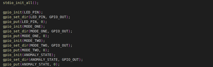
stdio_init_all();
gpio_init(LED_PIN);
gpio_set_dir(LED_PIN, GPIO_OUT);
gpio_put(LED_PIN, 0);
gpio_init(MODE_ONE);
gpio_set_dir(MODE_ONE, GPIO_OUT);
gpio_put(MODE_ONE, 0);
gpio_init(MODE_TWO);
gpio_set_dir(MODE_TWO, GPIO_OUT);
gpio_put(MODE_TWO, 0);
gpio_init(ANOMALY_STATE);
gpio_set_dir(ANOMALY_STATE, GPIO_OUT);
gpio_put(ANOMALY_STATE, 0);
i2c_init(i2c_default, 400 * 1000);
gpio_set_function(PICO_DEFAULT_I2C_SDA_PIN, GPIO_FUNC_I2C);
gpio_set_function(PICO_DEFAULT_I2C_SCL_PIN, GPIO_FUNC_I2C);
gpio_pull_up(PICO_DEFAULT_I2C_SDA_PIN);
gpio_pull_up(PICO_DEFAULT_I2C_SCL_PIN);
// Make the I2C pins available to picotool
bi_decl(bi_2pins_with_func(PICO_DEFAULT_I2C_SDA_PIN, PICO_DEFAULT_I2C_SCL_PIN, GPIO_FUNC_I2C));
mpu6050_reset();
int16_t acceleration[3];
if (EI_CLASSIFIER_RAW_SAMPLES_PER_FRAME != 3) {
ei_printf("ERR: EI_CLASSIFIER_RAW_SAMPLES_PER_FRAME should be equal to 3 (the 3 sensor axes)\n");
return 1;
}
while (true){
ei_printf("\nStarting inferencing in 2 seconds...\n");
sleep_ms(2000);
gpio_put(LED_PIN, 1);
ei_printf("Sampling...\n");
// Allocate a buffer here for the values we'll read from the IMU
float buffer[EI_CLASSIFIER_DSP_INPUT_FRAME_SIZE] = { 0 };
for (size_t ix = 0; ix < EI_CLASSIFIER_DSP_INPUT_FRAME_SIZE; ix += 3) {
// Determine the next tick (and then sleep later)
uint64_t next_tick = ei_read_timer_us() + (EI_CLASSIFIER_INTERVAL_MS * 1000);
mpu6050_read_raw(acceleration);
buffer[ix] = acceleration[0];
buffer[ix + 1] = acceleration[1];
buffer[ix + 2] = acceleration[2];
sleep_us(next_tick - ei_read_timer_us());
}
// Turn the raw buffer in a signal which we can the classify
signal_t signal;
int err = numpy::signal_from_buffer(buffer, EI_CLASSIFIER_DSP_INPUT_FRAME_SIZE, &signal);
if (err != 0) {
ei_printf("Failed to create signal from buffer (%d)\n", err);
return 1;
}
// Run the classifier
ei_impulse_result_t result = { 0 };
err = run_classifier(&signal, &result, debug_nn);
if (err != EI_IMPULSE_OK) {
ei_printf("ERR: Failed to run classifier (%d)\n", err);
return 1;
}
// print the predictions
ei_printf("Predictions ");
ei_printf("(DSP: %d ms., Classification: %d ms., Anomaly: %d ms.)",
result.timing.dsp, result.timing.classification, result.timing.anomaly);
ei_printf(": \n");
for (size_t ix = 0; ix < EI_CLASSIFIER_LABEL_COUNT; ix++) {
ei_printf(" %s: %.5f\n", result.classification[ix].label, result.classification[ix].value);
}
#if EI_CLASSIFIER_HAS_ANOMALY == 1
ei_printf(" anomaly score: %.3f\n", result.anomaly);
#endif
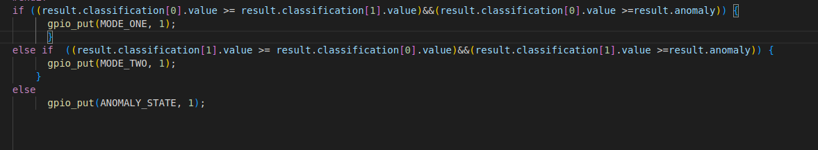
if ((result.classification[0].value >= result.classification[1].value)&&(result.classification[0].value >=result.anomaly)) {
gpio_put(MODE_ONE, 1);
}
else if ((result.classification[1].value >= result.classification[0].value)&&(result.classification[1].value >=result.anomaly)) {
gpio_put(MODE_TWO, 1);
}
else
gpio_put(ANOMALY_STATE, 1);
gpio_put(LED_PIN, 0);
}
#if !defined(EI_CLASSIFIER_SENSOR) || EI_CLASSIFIER_SENSOR != EI_CLASSIFIER_SENSOR_ACCELEROMETER
#error "Invalid model for current sensor"
#endif
return 0;
}