the coordinates of the Bbox given by Edge Impulse
the coordinates on a photo taken just after detection
(knowing that the detection photo is not accessible)
Have you addressed the problem?
Do you see what this is about?
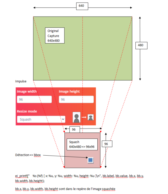
When the detection is made, we have: ei_printf(" %s (%f) [ x: %u, y: %u, width: %u, height: %u ]\n", bb.label, bb.value, bb.x, bb.y, bb.width, bb.height);
But what do the bb.x, bb.y, bb.width, bb.height values correspond to “in real life”?
just after detection we take a photo which we save with the coordinates of the bbox as a name.
I use Esp32Cam with Arduino IDE, so we don’t have the “inferenced image”
After detection, I take a photo and try to locate the hornet.
imagine that we make an impulse in 96x96
imagine that we take a 640x480 capture containing the object to be detected
the detection is made in 96x96 and gives coordinates bb.x, bb.y, bb.w and bb.h in this 96x96 frame
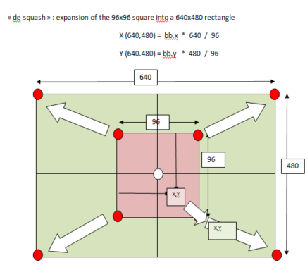
these coordinates must be expanded from 96x96 to 640x480 to find the detection on the original capture.
X(640.480) = bb.x * 640 / 96
Y (640.480) = bb.y * 480 / 96
Please tell me if this is correct.
To draw a Bounding Box (BB) on the original image we need to know how EdgeImpulse re-sized the image from 640x480 to 96x96 in the Input Block of the Impulse design.
I like you diagram! I think the method should work.
To overlay the BB on the image used for inference…
I assume your Arduino C code has something like:
// Setup "signal": sets the callback function on the "signal_t" structure to reference the inference buffer.
  ei::signal_t signal;
  signal.total_length = EI_CLASSIFIER_INPUT_WIDTH * EI_CLASSIFIER_INPUT_HEIGHT;
  signal.get_data     = &ei_camera_cutout_get_data;                               // This tells the "signal" where to get the sampled data from.
  static ei_impulse_result_t ei_result = { 0 };                                   // Local: "results" of Classifier(). This doesn't need to be global.
The data located at &ei_camera_cutout_get_data is the image that the camera captured and has been reduced to 96x96. You then modify the ei_camera_cutout_get_data data with the outline of the BB. If the Impulse is grayscale, then the outline can be all white or all black. If the Impulse is RGB then choose a color like cyan and change the pixels (aka the data in ei_camera_cutout_get_data) to match your BB. Then write out all the data held in located at&ei_camera_cutout_get_data to a BMP. BMPs will be much easier since there is no compression as is found in JPGs.
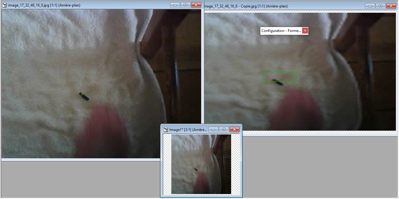
photos: on the left the photo after detection in 640x380,
at the bottom the same setting in 96x96,
on the right the 96x96 photo reverted to 640x380.
the coordinates of the detection bbox are given in the title of the file: 32_48_16_8.
On the 96x96 photo I traced the rectangle then I put the photo back in 640x380
and we find the rectangle in 210.190, that is to say in the homothety ratio 640/96 for X and 380/96 for Y.
@BARROISI am impressed at how fast you got to a working solution. You must be an excellent programmer.
Now that you are able to write the image to an SD card, you might want to draw the BB on the image saved to the SD card. Then in a post-processing task you can resize the inferenced image to any size you desire without worrying about the enlarged image size.
Thanks for your appreciation, but I’m nothing without my friends: Jody and Simone (aka EloquentArduino). They gave me their time and their knowledge, so we share your praise.
Let me add two things that come to me from Simone:
-1- recovering the detection frame ultimately has no interest: if we put it back in the original format, this double transformation makes it unusable. We can barely see the target. You might as well redo another image and place on it the rectangle given by detection and deformed by homothety.
-2- at no time do we introduce error calculations! And as Simone points out, “Edge Impulse outputs only multiples of 8. So when it says that bbox x,y is Eg. 32.48 it really could be anything from 32.48 to 39.55.” which puts the result into perspective.
As for the interesting functions that we use, I invite you to consult the EloquentArduino website: