Go to firmware-pi-rp2040/ThirdParty/Wire/src/Wire.h and change the SDA & SCL pin, as remark by RickorDD above.
If you read the readme in the firmware repo, it says you need to install the PICO_SDK in your machine, so git clone that repo in your machine, GitHub - raspberrypi/pico-sdk & set the path variable as where you put this pico sdk folder.
Back to your firmware folder, run the lines as in the readme. The output uf2 file will be located in the firmware-pi-rp2040/build folder.
FYI, my machine is windows10, and i ran the above in WSL Ubuntu 18.04.
After done the dataset collection, training, validation & compiling the arduino library in edge impulse studio, i was trying to run the inference example with my nano rp2040, the static buffer example sketch works well, serial report the classifier correctly. The problem i face now is, i can’t get any respond in serial when i run the ‘nano_ble33_sense_accelerometer_continuous’ sketch, which i’d modified
line#25, replace
& line#191, EI_CLASSIFIER_SENSOR_ACCELEROMETER to EL_CLASSIFIER_SENSOR_FUSION.
#if !defined(EI_CLASSIFIER_SENSOR) || EI_CLASSIFIER_SENSOR != EI_CLASSIFIER_SENSOR_FUSION   // EI_CLASSIFIER_SENSOR_ACCELEROMETER
#error "Invalid model for current sensor"
#endif
Any advice from anyone how to run inference with nano rp2040?
I am working with a Custom RP2040 board and I adapted the new firmware to make it work, also I changed the Inertial sensor code to support mine a (3-axis LIS3DH) and a PDM mic.
what is the right setting for PDM and Microphone Arduino Connect RP2040?
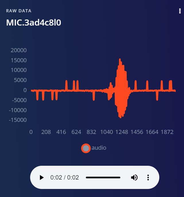
My mic on board running with 20000 Sampling Frequency and 512 SampleBuffer at a Sketch Example.
Erm. An official example for using microphone on RP2040 Connect suggests using 16000 Hz frequency. Therefore RP2040 Connect microphone should support this frequency.
If the mic on your board does not support 16000 Hz recording, it means that you likely have a different board.
I found the Bug.
Decimation could be 128 not 64
There is a Codesnippet in PDM.cpp thats set to 64. Why?
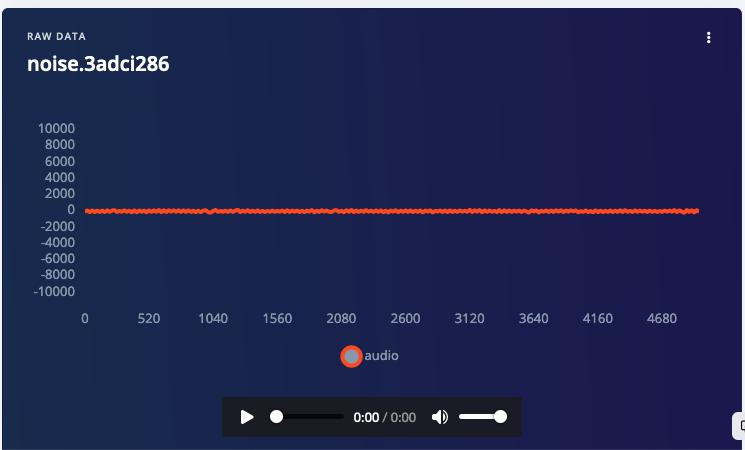
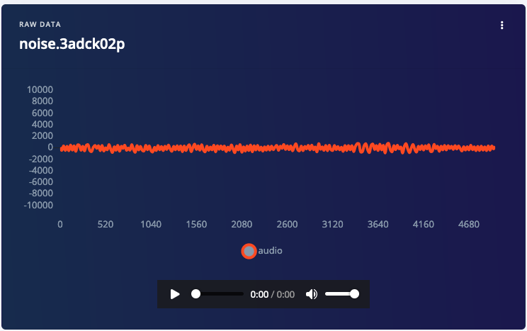
I disable then MIC Data send to Edge Impulse.
But only set 16000Hz not 8000Hz the Record is ok.
The PDM library is taken from Arduino mbed core for RP2040. As your rightly pointed, the switch to 64 decimation factor was added by this PR https://github.com/arduino/ArduinoCore-mbed/issues/289
If left at 128 for 16000 Hz sampling rate, the clock frequency would be too high for RP2040 Connect mic.
I have tested the microphone ingestion just now and it works perfectly.
this is for quiet room at 8000 Hz
Would you like to send pictures of your board to see if it the same revision?
Regardless, if even Arduino Mic Plotter example sketch does not work for you, it is likely an issue on hardware side, that needs to be addressed by Arduino.
To reiterate - if you look at the code, you’ll see that if you set frequency to 16000 Hz, the decimation rate will be set to 64. If frequency is 8000 Hz, then decimation rate is 128.
The microphone on Connect RP2040 will not support 16000Hz and 128 decimation rate - it exceeds the microphone sampling frequency limit, calculated as sampleRate * decimation * 2.
The problem you’re having is likely hardware one - again, I suggest take it to Arduino team. The best I can do here is to record which hardware do you have exactly.
Maybe the Arduino team’s decision to use the same microphone hardware as the BLE33 Sense wasn’t too good after all. Because the BLE33 works well with 16000Hz, only that unfortunately it does not have a Wifi module. There seems to be boards where it works and which ones where it doesn’t. The Nicla has the MP34DT06J not the MP34DT05 but the same library.
Hello Sir,
Thanks for your previous comment regarding the procedure to make firmware for Nano RP2040. I tried it and I was successful in it. Thanks to you. I have started training the model. However, I am facing one problem. When model training was done, I build library for the model. In that library, I only found nano_ble33_accelerometer. I didn’t found nano_ble33_accelerometer_continuous. Kindly guide me through this.
In addition, could you please tell me why did you change line #191 to EI_CLASSIFIER_SENSOR_FUSION. Kindly reply. Thanks in Advance
Hi @Jatin, thanks for your message. You can see my write-up in hackster here. The reason I change line #191 to EI_CLASSIFIER_SENSOR_FUSION is because I want to use both accelerometer & gyro data.
As for the continuous example, I had just downloaded the library from my project and there is no continuous example anymore, not sure why EI remove that. But if I recall correctly, I remember that example didn’t work well for my project (forgot whether is run out of memory or just didn’t work). Hopefully EI will reach out to you to answer your question.
Hi - I’m sorry to be confused here. I believe you developed and now support the Arduino RP2040 Connect, and refer to the documentation. The documentation also states full support, but in the same documentation refers support for Arduino Connect to “Raspberry Pi RP2040 - Edge Impulse Documentation”, where it says ‘no support for mic’, for example. The official Pi 2040 firmware does not appear to recognize the Arduino Connect, thinks it’s a Pi board.
I have both boards, but would like to use the Arduino Connect. Do you recommend I continue with the Pi board, or is there a separate build for the Arduino Connect?
Thank you very much!
Hey folks I am a newbie on this and kinda losing my mind trying to get my Adafruit LSM6DSOX ST work on edge impulse. I would really appreciate if you could help me. I am trying to read accelerometer and gyroscope values from Adafruit LSM6DSOX which is connected to Adafruit Feather RP2040. When I make the changes above mentioned in Wire.h, after flashing I get this error -
[SER] Could not find any devices connected over serial port
Did you load the pre-compiled RP2040 firmware from Edge Impulse onto your board? Raspberry Pi RP2040 | Edge Impulse Documentation You need this running on your RP2040 board prior to connect with the Edge Impulse CLI daemon.
Also, note that the firmware listed above only works with the sensors listed here: Raspberry Pi RP2040 | Edge Impulse Documentation. It will not work with the LSM9DSOX. So, you will need to either use an LSM6DS3 or write your own firmware to capture and store samples or switch to an LSM6DS3.
If you write your own firmware, note that you can use the Data forwarder to capture data from the serial and send it to your Edge Impulse project.
Support for Arduino RP2040 Connect was added to the official RP2040 firmware for Edge Impulse. That includes data acquisition and model inference support for:
onboard MP34DT05 microphone
onboard ST LSM6DSOX 6-axis IMU
the sensors described above still can be connected
However I really have no idea what it has to do with the original topic discussion. @dataexplorer007 please create a separate topic with detailed description of the problem, thanks!